

Consulte las especificaciones para obtener detalles del producto.
8520DYLFT
Overview
- Category: Electronic Component
- Use: Integrated Circuit
- Characteristics: High-performance, Low-power consumption
- Package: DIP (Dual In-line Package)
- Essence: Digital Logic Gate
- Packaging/Quantity: Tape and Reel / 1000 units per reel
Specifications and Parameters
- Supply Voltage: 3.3V
- Operating Temperature: -40°C to +85°C
- Input Voltage: 0V to Vcc
- Output Voltage: 0V to Vcc
- Maximum Operating Frequency: 50MHz
- Propagation Delay: 5ns
- Power Dissipation: 100mW
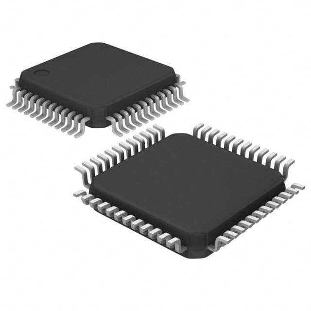
Pin Configuration
The 8520DYLFT integrated circuit has a total of 14 pins. The pin configuration is as follows:
- GND (Ground)
- A0 (Input A0)
- A1 (Input A1)
- A2 (Input A2)
- B0 (Input B0)
- B1 (Input B1)
- B2 (Input B2)
- C0 (Output C0)
- C1 (Output C1)
- C2 (Output C2)
- Vcc (Power Supply)
- NC (No Connection)
- NC (No Connection)
- GND (Ground)
Functional Characteristics
The 8520DYLFT is a high-performance digital logic gate integrated circuit. It operates as a 3-input AND gate with open-drain outputs. The inputs (A0, A1, A2 and B0, B1, B2) are used to control the logic operation, and the outputs (C0, C1, C2) provide the logical result. The IC is designed to operate at low power consumption while maintaining high-speed performance.
Advantages and Disadvantages
Advantages: - High-performance operation - Low-power consumption - Compact DIP package for easy integration - Open-drain outputs for flexible interfacing
Disadvantages: - Limited to 3-input AND gate functionality - Not suitable for applications requiring complex logic operations
Applicable Range of Products
The 8520DYLFT is commonly used in various digital systems, including but not limited to: - Microcontrollers - Programmable Logic Controllers (PLCs) - Digital Signal Processors (DSPs) - Communication devices - Consumer electronics
Working Principles
The 8520DYLFT operates based on the principles of digital logic gates. It performs the logical AND operation on the input signals (A0, A1, A2 and B0, B1, B2) and generates the corresponding output signals (C0, C1, C2). The open-drain outputs allow for easy interfacing with other components or devices.
Detailed Application Field Plans
The 8520DYLFT can be applied in various fields, such as: 1. Industrial Automation: Used in PLCs for controlling and monitoring industrial processes. 2. Embedded Systems: Integrated into microcontroller-based systems for performing specific logic operations. 3. Communication Systems: Employed in communication devices for signal processing and data manipulation. 4. Automotive Electronics: Utilized in automotive control units for implementing specific logic functions. 5. Consumer Electronics: Incorporated into electronic devices for performing digital logic operations.
Detailed Alternative Models
Some alternative models to the 8520DYLFT include: - 74HC11: Triple 3-input AND gate with standard CMOS technology. - SN74LS11: Triple 3-input AND gate with low-power Schottky TTL technology. - CD4073B: Triple 3-input AND gate with CMOS technology. - MC14011B: Quad 2-input NAND gate with CMOS technology. - CD4081B: Quad 2-input AND gate with CMOS technology.
5 Common Technical Questions and Answers
Q: What is the maximum operating frequency of the 8520DYLFT? A: The maximum operating frequency is 50MHz.
Q: Can the 8520DYLFT be used in automotive applications? A: Yes, it can be used in automotive electronics for specific logic functions.
Q: What is the power dissipation of the 8520DYLFT? A: The power dissipation is 100mW.
Q: How many pins does the 8520DYLFT have? A: It has a total of 14 pins.
Q: What is the temperature range for the 8520DYLFT? A: The operating temperature range is -40°C to +85°C.
This encyclopedia entry provides an overview of the 8520DYLFT integrated circuit, including its basic information, specifications,