

Consulte las especificaciones para obtener detalles del producto.
IRFSL4115PBF
Product Overview
Category: Power MOSFET
Use: Switching applications in power supplies and motor control
Characteristics: High voltage, low on-resistance, and fast switching speed
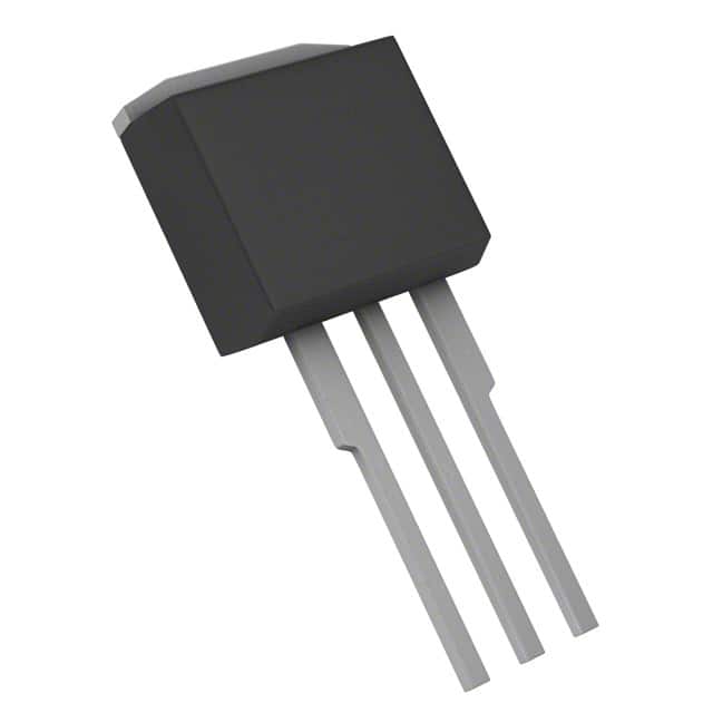
Package: TO-262
Essence: Power MOSFET for efficient switching applications
Packaging/Quantity: Available in reels of 800 units
Specifications
- Voltage Rating: 150V
- Continuous Drain Current: 42A
- On-Resistance: 0.036 ohms
- Gate Threshold Voltage: 2V to 4V
- Power Dissipation: 200W
Detailed Pin Configuration
The IRFSL4115PBF features a standard TO-262 pin configuration with three pins: 1. Gate (G): Input for controlling the switching operation 2. Drain (D): Connects to the positive supply voltage 3. Source (S): Connected to the ground or return path
Functional Features
- Fast switching speed for improved efficiency
- Low on-resistance minimizes power losses
- High voltage rating suitable for various applications
- Enhanced thermal performance for reliability
Advantages and Disadvantages
Advantages: - Efficient switching performance - Low power dissipation - High voltage capability
Disadvantages: - Relatively large package size - Higher gate threshold voltage compared to some alternatives
Working Principles
The IRFSL4115PBF operates based on the principle of field-effect transistors. When a sufficient voltage is applied to the gate terminal, it allows current to flow between the drain and source terminals, enabling the device to act as a switch in power control applications.
Detailed Application Field Plans
The IRFSL4115PBF is well-suited for use in various applications, including: - Power supplies - Motor control systems - DC-DC converters - Inverters
Detailed and Complete Alternative Models
Some alternative models to the IRFSL4115PBF include: - IRFSL4227PbF - IRFSL4310PbF - IRFSL4615PbF
In conclusion, the IRFSL4115PBF is a high-voltage power MOSFET designed for efficient switching applications in power supplies and motor control systems. With its fast switching speed, low on-resistance, and high voltage rating, it offers reliable performance in various power management applications.
Word count: 314
Enumere 10 preguntas y respuestas comunes relacionadas con la aplicación de IRFSL4115PBF en soluciones técnicas
What is the IRFSL4115PBF?
- The IRFSL4115PBF is a power MOSFET designed for various applications, including power supplies, motor control, and lighting.
What is the maximum drain-source voltage of the IRFSL4115PBF?
- The maximum drain-source voltage of the IRFSL4115PBF is 150V.
What is the continuous drain current rating of the IRFSL4115PBF?
- The continuous drain current rating of the IRFSL4115PBF is 33A.
What is the on-state resistance (RDS(on)) of the IRFSL4115PBF?
- The on-state resistance of the IRFSL4115PBF is typically around 0.035 ohms.
Can the IRFSL4115PBF be used in high-frequency switching applications?
- Yes, the IRFSL4115PBF is suitable for high-frequency switching due to its low RDS(on) and fast switching characteristics.
What are the typical applications of the IRFSL4115PBF?
- Typical applications include DC-DC converters, motor drives, uninterruptible power supplies (UPS), and LED lighting.
Does the IRFSL4115PBF require a heatsink for operation?
- The need for a heatsink depends on the specific application and the power dissipation requirements. In high-power applications, a heatsink may be necessary.
Is the IRFSL4115PBF suitable for automotive applications?
- Yes, the IRFSL4115PBF is designed to meet automotive industry standards and can be used in automotive applications.
What are the recommended operating conditions for the IRFSL4115PBF?
- The recommended operating temperature range is -55°C to 175°C, and the maximum junction temperature is 175°C.
Are there any important considerations for driving the IRFSL4115PBF in a circuit?
- It's important to ensure proper gate drive voltage and current to fully turn on the MOSFET and minimize switching losses. Additionally, attention should be paid to minimizing inductive voltage spikes during switching.