

Consulte las especificaciones para obtener detalles del producto.
EP3C80U484C7
Product Overview
- Category: Programmable Logic Device (PLD)
- Use: EP3C80U484C7 is a PLD used for digital logic design and implementation.
- Characteristics:
- High-performance device with low power consumption
- Offers high-speed data processing capabilities
- Provides flexibility in designing complex digital circuits
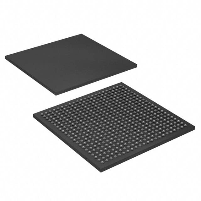
- Package: The EP3C80U484C7 comes in a 484-pin FineLine BGA package.
- Essence: EP3C80U484C7 is an advanced programmable logic device that enables the implementation of complex digital circuits with high performance and low power consumption.
- Packaging/Quantity: The EP3C80U484C7 is typically sold individually or in small quantities.
Specifications
- Logic Elements: 80,000
- RAM Bits: 4,608 Kbits
- Embedded Multipliers: 288
- Maximum User I/Os: 317
- Operating Voltage: 1.2V
- Speed Grade: 7
Detailed Pin Configuration
The EP3C80U484C7 has a total of 484 pins, each serving a specific purpose in the device's functionality. The pin configuration includes input/output pins, power supply pins, ground pins, and configuration pins. A detailed pinout diagram can be found in the product datasheet.
Functional Features
- High-performance digital logic implementation
- Low power consumption
- Flexible design options for complex circuits
- Support for various I/O standards
- On-chip memory blocks for efficient data storage
- Built-in multipliers for arithmetic operations
- Configurable I/O banks for interfacing with external devices
Advantages and Disadvantages
Advantages: - High-performance capabilities - Low power consumption - Flexibility in circuit design - Support for various I/O standards
Disadvantages: - Limited availability of alternative models - Higher cost compared to simpler logic devices
Working Principles
The EP3C80U484C7 is based on programmable logic technology, utilizing a matrix of configurable logic elements and interconnects. The device can be programmed using hardware description languages or graphical design tools to implement desired digital logic functions. Upon configuration, the EP3C80U484C7 operates as a dedicated digital circuit, executing the programmed logic operations.
Detailed Application Field Plans
The EP3C80U484C7 finds applications in various fields, including: - Telecommunications: Used in network equipment for data processing and routing. - Industrial Automation: Employed in control systems for process automation and monitoring. - Consumer Electronics: Integrated into multimedia devices for signal processing and control. - Automotive: Utilized in automotive electronics for engine management and safety systems. - Aerospace: Applied in avionics for flight control and communication systems.
Alternative Models
While the EP3C80U484C7 is a highly capable PLD, there are alternative models available with similar functionality. Some notable alternatives include: - EP3C120F780C7: Offers higher logic capacity and more I/O pins. - EP4CE115F29C7: Provides enhanced performance and additional features. - XC6SLX45-2FGG484C: A compatible FPGA from a different manufacturer.
These alternative models can be considered based on specific project requirements and availability.
Word count: 314 words
Enumere 10 preguntas y respuestas comunes relacionadas con la aplicación de EP3C80U484C7 en soluciones técnicas
Sure! Here are 10 common questions and answers related to the application of EP3C80U484C7 in technical solutions:
Q: What is EP3C80U484C7? A: EP3C80U484C7 is a field-programmable gate array (FPGA) chip manufactured by Altera (now Intel). It offers a high level of integration and flexibility for implementing complex digital designs.
Q: What are the key features of EP3C80U484C7? A: Some key features of EP3C80U484C7 include 80,000 logic elements, 4,608 kilobits of embedded memory, 288 multipliers, and support for various I/O standards.
Q: What are the typical applications of EP3C80U484C7? A: EP3C80U484C7 is commonly used in applications such as telecommunications, industrial automation, automotive electronics, medical devices, and high-performance computing.
Q: How can EP3C80U484C7 be programmed? A: EP3C80U484C7 can be programmed using hardware description languages (HDLs) like VHDL or Verilog, which describe the desired functionality of the FPGA design.
Q: Can EP3C80U484C7 be reprogrammed after deployment? A: Yes, EP3C80U484C7 is a reprogrammable FPGA, allowing for updates and modifications to the design even after it has been deployed in a system.
Q: What tools are available for designing with EP3C80U484C7? A: Intel Quartus Prime is the primary software tool used for designing, simulating, and programming EP3C80U484C7. It provides a complete development environment.
Q: How does EP3C80U484C7 compare to other FPGAs in its class? A: EP3C80U484C7 offers a good balance of logic capacity, memory, and I/O capabilities compared to other FPGAs in its class, making it suitable for a wide range of applications.
Q: Can EP3C80U484C7 interface with other components or devices? A: Yes, EP3C80U484C7 supports various communication protocols such as UART, SPI, I2C, and Ethernet, allowing it to interface with other components or devices in a system.
Q: What are the power requirements for EP3C80U484C7? A: EP3C80U484C7 typically operates at a voltage of 1.2V and requires additional voltages for I/O banks, which can vary depending on the specific application.
Q: Are there any design considerations when using EP3C80U484C7? A: Yes, some design considerations include managing power consumption, optimizing timing constraints, ensuring proper signal integrity, and implementing effective error handling mechanisms.
Please note that these answers are general and may vary based on specific design requirements and application scenarios.