

Consulte las especificaciones para obtener detalles del producto.
ICL7107RCPL
Product Overview
Category
ICL7107RCPL belongs to the category of integrated circuits (ICs).
Use
This product is commonly used in electronic devices for analog-to-digital conversion.
Characteristics
- High accuracy and resolution
- Low power consumption
- Easy to use
- Wide operating voltage range
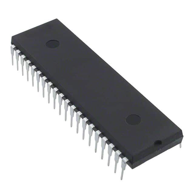
Package
ICL7107RCPL is available in a 40-pin plastic dual in-line package (DIP).
Essence
The essence of ICL7107RCPL lies in its ability to convert analog signals into digital data with high precision and efficiency.
Packaging/Quantity
This product is typically packaged in reels or tubes, with a quantity of 250 units per reel/tube.
Specifications
- Resolution: 3.5 digits
- Supply Voltage Range: 4V to 6V
- Operating Temperature Range: -40°C to +85°C
- Conversion Time: 100ms
- Reference Voltage: 2.56V
Detailed Pin Configuration
- V+ (Positive Power Supply)
- IN+ (Positive Analog Input)
- IN- (Negative Analog Input)
- REF HI (Reference Voltage High)
- REF LO (Reference Voltage Low)
- AGND (Analog Ground)
- DGND (Digital Ground)
- A/D OUT (Digital Output)
- A/D CLK (Clock Input)
- A/D CS (Chip Select Input)
- A/D RST (Reset Input)
- A/D MODE (Mode Select Input)
- D1 (Segment D1 Output)
- D2 (Segment D2 Output)
- D3 (Segment D3 Output)
- D4 (Segment D4 Output)
- D5 (Segment D5 Output)
- D6 (Segment D6 Output)
- D7 (Segment D7 Output)
- D8 (Segment D8 Output)
- D9 (Segment D9 Output)
- D10 (Segment D10 Output)
- D11 (Segment D11 Output)
- D12 (Segment D12 Output)
- D13 (Segment D13 Output)
- D14 (Segment D14 Output)
- D15 (Segment D15 Output)
- D16 (Segment D16 Output)
- D17 (Segment D17 Output)
- D18 (Segment D18 Output)
- D19 (Segment D19 Output)
- D20 (Segment D20 Output)
- D21 (Segment D21 Output)
- D22 (Segment D22 Output)
- D23 (Segment D23 Output)
- D24 (Segment D24 Output)
- D25 (Segment D25 Output)
- D26 (Segment D26 Output)
- D27 (Segment D27 Output)
- V- (Negative Power Supply)
Functional Features
- High-resolution analog-to-digital conversion
- Internal voltage reference for accurate measurements
- Multiplexed display outputs for easy visualization
- Low power consumption for energy-efficient designs
- Built-in clock and control circuitry for simplified operation
Advantages and Disadvantages
Advantages
- High accuracy and resolution
- Wide operating voltage range
- Easy to use and integrate into electronic systems
- Low power consumption for energy efficiency
Disadvantages
- Limited number of digital output pins
- Requires external components for proper operation
- Relatively higher cost compared to some alternative models
Working Principles
ICL7107RCPL operates based on the principle of successive approximation analog-to-digital conversion. It uses an internal voltage reference to compare the input analog signal and generates a digital output representing the measured value. The conversion process is controlled by an internal clock and control circuitry.
Detailed Application Field Plans
ICL7107RCPL finds applications in various fields, including: 1. Digital multimeters 2. Data acquisition systems 3. Process control instruments 4. Industrial automation 5. Medical equipment 6. Automotive electronics 7. Power monitoring devices 8. Battery chargers 9. Test and measurement equipment 10. Consumer electronics
Detailed and Complete Alternative Models
Some alternative models to ICL7107RCPL include: - ADC0804 - MAX11645 - MCP3204 - TLC549 - ADS1115 - LTC2400 - HX711 - AD7791 - STM32F103C8T6 (microcontroller with built-in ADC)
These alternative models offer similar functionality and can be used as substitutes depending on specific requirements and design considerations.
Word count: 550 words
Enumere 10 preguntas y respuestas comunes relacionadas con la aplicación de ICL7107RCPL en soluciones técnicas
Sure! Here are 10 common questions and answers related to the application of ICL7107RCPL in technical solutions:
Q: What is the ICL7107RCPL? A: The ICL7107RCPL is a high-performance, low-power, 3.5-digit analog-to-digital converter (ADC) commonly used in digital panel meters and other measurement applications.
Q: What is the operating voltage range of the ICL7107RCPL? A: The ICL7107RCPL operates within a voltage range of 4V to 6.5V.
Q: Can the ICL7107RCPL measure negative voltages? A: No, the ICL7107RCPL can only measure positive voltages. If you need to measure negative voltages, you may need additional circuitry such as an op-amp or level shifter.
Q: How accurate is the ICL7107RCPL? A: The ICL7107RCPL has a typical accuracy of ±1 count, which means it can display the measured value with a precision of 1 part in 2000.
Q: What is the maximum input voltage that the ICL7107RCPL can handle? A: The ICL7107RCPL can handle a maximum input voltage of 200mV when using an external voltage divider.
Q: Can the ICL7107RCPL be used for temperature measurements? A: Yes, the ICL7107RCPL can be used for temperature measurements by interfacing it with a temperature sensor such as a thermocouple or a thermistor.
Q: Does the ICL7107RCPL require any external components? A: Yes, the ICL7107RCPL requires external components such as resistors, capacitors, and a reference voltage source to function properly.
Q: Can the ICL7107RCPL be used in battery-powered applications? A: Yes, the ICL7107RCPL is designed to operate with low power consumption, making it suitable for battery-powered applications.
Q: What is the maximum conversion rate of the ICL7107RCPL? A: The ICL7107RCPL has a maximum conversion rate of 3 conversions per second (3Hz).
Q: Are there any application notes or example circuits available for the ICL7107RCPL? A: Yes, the manufacturer provides application notes and example circuits in the datasheet of the ICL7107RCPL, which can help you understand its usage and implementation in various technical solutions.
Please note that these answers are general and may vary depending on specific circuit configurations and requirements. It's always recommended to refer to the datasheet and consult with an experienced engineer for accurate information and guidance.