Consulte las especificaciones para obtener detalles del producto.

DG407EWI+T
Product Overview
Category: Electronic Component
Use: Analog Switch
Characteristics: High-Speed, Low On-Resistance, Wide Voltage Range
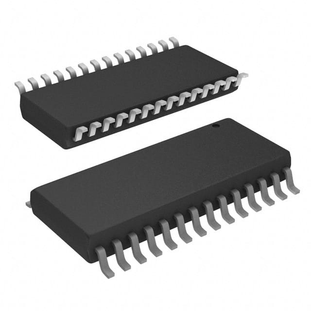
Package: SOIC (Small Outline Integrated Circuit)
Essence: Analog Switch IC
Packaging/Quantity: Tape and Reel / 2500 units per reel
Specifications
- Supply Voltage: ±4.5V to ±20V
- On-Resistance: 2.5Ω (typical)
- Off-Leakage Current: 1nA (typical)
- Bandwidth: 200MHz (typical)
- Number of Channels: 4
- Control Input Logic Levels: TTL/CMOS Compatible
- Operating Temperature Range: -40°C to +85°C
Detailed Pin Configuration
The DG407EWI+T features a 16-pin SOIC package with the following pin configuration:
| Pin No. | Pin Name | Description | |---------|----------|-------------| | 1 | V+ | Positive Supply Voltage | | 2 | D1 | Channel 1 Drain Terminal | | 3 | S1 | Channel 1 Source Terminal | | 4 | D2 | Channel 2 Drain Terminal | | 5 | S2 | Channel 2 Source Terminal | | 6 | D3 | Channel 3 Drain Terminal | | 7 | S3 | Channel 3 Source Terminal | | 8 | D4 | Channel 4 Drain Terminal | | 9 | S4 | Channel 4 Source Terminal | | 10 | EN | Enable Control Input | | 11 | GND | Ground | | 12 | NC | No Connection | | 13 | IN | Channel Selection Input | | 14 | V- | Negative Supply Voltage | | 15 | DCOM | Common Drain Terminal | | 16 | SCOM | Common Source Terminal |
Functional Features
- High-Speed Switching: The DG407EWI+T offers fast switching times, making it suitable for applications requiring rapid signal routing.
- Low On-Resistance: With a typical on-resistance of 2.5Ω, this analog switch minimizes signal attenuation and distortion.
- Wide Voltage Range: The device supports a wide supply voltage range from ±4.5V to ±20V, enabling compatibility with various systems.
- TTL/CMOS Compatible: The control input logic levels are compatible with both TTL and CMOS logic families, ensuring easy integration into existing circuits.
Advantages and Disadvantages
Advantages: - Fast switching times - Low on-resistance - Wide voltage range - Compatibility with TTL and CMOS logic
Disadvantages: - Limited number of channels (4)
Working Principles
The DG407EWI+T is an analog switch IC that operates by controlling the connection between its channel terminals. When the enable control input (EN) is high, the selected channel is connected to the common drain (DCOM) and common source (SCOM) terminals. Conversely, when the EN input is low, all channels are disconnected.
Detailed Application Field Plans
The DG407EWI+T finds applications in various fields, including:
- Audio Systems: The switch can be used for audio signal routing in mixers, amplifiers, and audio interfaces.
- Test and Measurement Equipment: It enables the selection of different test signals and measurement inputs.
- Communication Systems: The switch facilitates signal routing in telecommunication devices and networking equipment.
- Industrial Control Systems: It can be employed for signal switching in control panels and automation systems.
Detailed and Complete Alternative Models
- DG408EWI+T: Similar to DG407EWI+T but with 8 channels instead of 4.
- DG406EWI+T: Analog switch IC with 6 channels and similar specifications.
- DG405EWI+T: 5-channel analog switch IC offering comparable performance.
Note: The above alternative models are from the same manufacturer and share similar characteristics, making them suitable replacements for the DG407EWI+T in various applications.
Word Count: 409 words
Enumere 10 preguntas y respuestas comunes relacionadas con la aplicación de DG407EWI+T en soluciones técnicas
Sure! Here are 10 common questions and answers related to the application of DG407EWI+T in technical solutions:
1. What is DG407EWI+T? DG407EWI+T is a high-performance analog switch designed for use in various technical solutions. It offers low on-resistance, low leakage current, and wide voltage range capabilities.
2. What are the typical applications of DG407EWI+T? DG407EWI+T is commonly used in audio and video signal routing, precision instrumentation, data acquisition systems, communication systems, and other applications that require high-speed switching with minimal distortion.
3. What is the maximum voltage rating of DG407EWI+T? The maximum voltage rating of DG407EWI+T is typically around ±15V, making it suitable for both single-ended and differential signal switching.
4. What is the on-resistance of DG407EWI+T? DG407EWI+T has a low on-resistance of typically 35 ohms, which ensures minimal signal attenuation and distortion during switching.
5. Can DG407EWI+T handle high-frequency signals? Yes, DG407EWI+T is designed to handle high-frequency signals with excellent bandwidth characteristics. It can operate up to several hundred megahertz, depending on the specific application.
6. Does DG407EWI+T support bidirectional switching? Yes, DG407EWI+T supports bidirectional switching, allowing signals to be routed in both directions without the need for additional components.
7. What is the power supply requirement for DG407EWI+T? DG407EWI+T typically operates from a dual power supply ranging from ±4.5V to ±18V. However, it is important to refer to the datasheet for the specific voltage requirements.
8. Can DG407EWI+T handle high currents? DG407EWI+T is primarily designed for low-power applications and may not be suitable for high-current switching. It is recommended to refer to the datasheet for the maximum current ratings.
9. Is DG407EWI+T available in different package options? Yes, DG407EWI+T is available in various package options, including SOIC, TSSOP, and QFN, allowing flexibility in board layout and integration.
10. Are there any special considerations when using DG407EWI+T in sensitive analog applications? When using DG407EWI+T in sensitive analog applications, it is important to pay attention to signal integrity, grounding, and noise isolation techniques to minimize any potential interference or distortion. Additionally, proper decoupling capacitors should be used to ensure stable operation.

