

Consulte las especificaciones para obtener detalles del producto.
AT24CS08-STUM-T
Product Overview
- Category: Integrated Circuit (IC)
- Use: Non-volatile Memory
- Characteristics: Serial EEPROM, 8-Kbit (1024 x 8) memory size
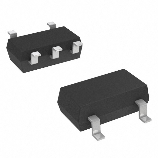
- Package: Surface Mount (STUM)
- Essence: Stores and retrieves data electronically even when power is turned off
- Packaging/Quantity: Tape and Reel, 3000 pieces per reel
Specifications
- Memory Size: 8-Kbit (1024 x 8)
- Interface: I2C
- Operating Voltage: 1.7V to 5.5V
- Operating Temperature Range: -40°C to +85°C
- Write Endurance: 1 Million cycles
- Data Retention: 100 Years
- Package Dimensions: 2mm x 3mm
- Lead Count: 8
Pin Configuration
The AT24CS08-STUM-T has the following pin configuration:
| Pin Number | Pin Name | Description | |------------|----------|-------------| | 1 | A0 | Address Input Bit 0 | | 2 | A1 | Address Input Bit 1 | | 3 | A2 | Address Input Bit 2 | | 4 | VSS | Ground | | 5 | SDA | Serial Data Input/Output | | 6 | SCL | Serial Clock Input | | 7 | WP | Write Protect | | 8 | VCC | Power Supply |
Functional Features
- Low-power CMOS technology for low standby current consumption
- Two-wire serial interface for easy integration with microcontrollers
- Self-timed write cycle with auto-erase before write operation
- Software write protection of the entire memory array
- Hardware write protection using the WP pin
- 32-byte page write mode for faster data transfers
Advantages and Disadvantages
Advantages: - Non-volatile memory retains data even without power - Small package size allows for space-efficient designs - Low power consumption extends battery life - Easy integration with microcontrollers using I2C interface
Disadvantages: - Limited storage capacity compared to other memory options - Slower write speed compared to some other memory technologies
Working Principles
The AT24CS08-STUM-T is a serial EEPROM that uses electrically erasable and programmable memory cells to store data. It communicates with the microcontroller through the I2C interface, allowing for easy read and write operations. The memory cells can be individually addressed, allowing selective access to specific data. The device operates on low power and has built-in write protection features to prevent accidental data modification.
Detailed Application Field Plans
The AT24CS08-STUM-T is commonly used in various applications, including but not limited to:
- Consumer Electronics: Used for storing configuration settings, user preferences, and firmware updates in devices such as TVs, set-top boxes, and audio systems.
- Industrial Automation: Used for storing calibration data, sensor readings, and system parameters in industrial control systems and PLCs.
- Automotive: Used for storing vehicle-specific data, such as mileage, service history, and security information in automotive electronics.
- Medical Devices: Used for storing patient data, device configurations, and firmware updates in medical equipment like monitors, pumps, and diagnostic devices.
Detailed and Complete Alternative Models
- AT24CS01: 1-Kbit (128 x 8) Serial EEPROM
- AT24CS02: 2-Kbit (256 x 8) Serial EEPROM
- AT24CS04: 4-Kbit (512 x 8) Serial EEPROM
- AT24CS16: 16-Kbit (2048 x 8) Serial EEPROM
- AT24CS32: 32-Kbit (4096 x 8) Serial EEPROM
These alternative models offer different memory sizes to suit various application requirements.
Word count: 436 words
Enumere 10 preguntas y respuestas comunes relacionadas con la aplicación de AT24CS08-STUM-T en soluciones técnicas
Sure! Here are 10 common questions and answers related to the application of AT24CS08-STUM-T in technical solutions:
Q: What is AT24CS08-STUM-T? A: AT24CS08-STUM-T is a serial EEPROM (Electrically Erasable Programmable Read-Only Memory) chip manufactured by Microchip Technology. It has a storage capacity of 8 kilobits (1 kilobyte) and operates on the I2C communication protocol.
Q: What are some typical applications of AT24CS08-STUM-T? A: AT24CS08-STUM-T is commonly used for storing configuration data, calibration values, and other small amounts of non-volatile data in various electronic devices such as microcontrollers, sensors, and industrial equipment.
Q: How do I interface with AT24CS08-STUM-T? A: AT24CS08-STUM-T communicates using the I2C bus protocol. You can connect it to your microcontroller or other I2C-compatible device using two wires - SDA (Serial Data Line) and SCL (Serial Clock Line).
Q: What is the operating voltage range of AT24CS08-STUM-T? A: AT24CS08-STUM-T operates within a voltage range of 1.7V to 5.5V, making it compatible with a wide range of systems.
Q: Can I write data to AT24CS08-STUM-T multiple times? A: Yes, AT24CS08-STUM-T supports both read and write operations. You can write data to it multiple times, up to its specified endurance limit.
Q: What is the endurance limit of AT24CS08-STUM-T? A: The endurance limit of AT24CS08-STUM-T is typically specified as 1 million write cycles. This means you can write data to it up to 1 million times before the memory cells start to degrade.
Q: How fast can I read and write data to AT24CS08-STUM-T? A: The maximum clock frequency for AT24CS08-STUM-T is 400 kHz, allowing for relatively fast data transfer. However, the actual speed may depend on the capabilities of your microcontroller or I2C bus.
Q: Is AT24CS08-STUM-T resistant to data corruption during power loss? A: Yes, AT24CS08-STUM-T has built-in features like write protection and a hardware write-protect pin that help prevent data corruption during power loss or other unexpected events.
Q: Can I use multiple AT24CS08-STUM-T chips in the same system? A: Yes, you can use multiple AT24CS08-STUM-T chips in the same system by assigning unique I2C addresses to each chip. The AT24CS08-STUM-T supports up to 8 different I2C addresses.
Q: Are there any limitations or considerations when using AT24CS08-STUM-T? A: Some considerations include the limited storage capacity (8 kilobits), the need for an external pull-up resistor on the SDA and SCL lines, and ensuring proper voltage levels and timing requirements are met for reliable communication.
Please note that these answers are general and may vary depending on specific implementation details and datasheet specifications.