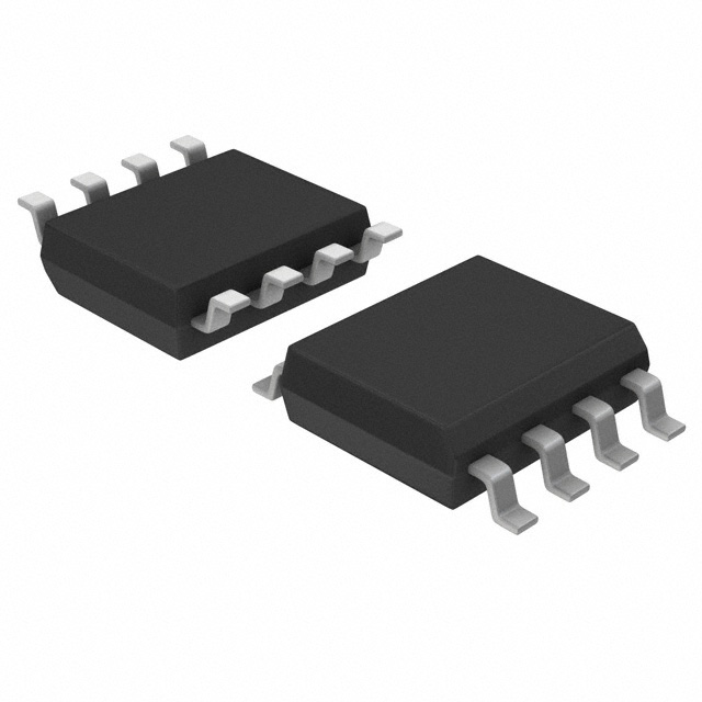
Consulte las especificaciones para obtener detalles del producto.

PCA9533D/01,118
Product Overview
- Category: Integrated Circuit (IC)
- Use: Digital I/O Expander
- Characteristics: Low-voltage 16-bit I2C-bus and SMBus I/O expander with interrupt output and configuration registers
- Package: SOIC (Small Outline Integrated Circuit)
- Essence: Provides additional digital input/output (I/O) pins for microcontrollers or other devices
- Packaging/Quantity: Available in tape and reel packaging, quantity depends on the supplier
Specifications
- Supply Voltage: 1.65V to 5.5V
- Number of I/O Pins: 16
- I2C-bus Interface: Compatible with I2C-bus and SMBus protocols
- Interrupt Output: Allows efficient communication between the PCA9533D/01,118 and the host device
- Configuration Registers: Enable customization of various features such as polarity inversion, input/output direction, and more
Detailed Pin Configuration
The PCA9533D/01,118 has a total of 16 pins. The pin configuration is as follows:
- A0: Address Input Bit 0
- A1: Address Input Bit 1
- A2: Address Input Bit 2
- INT: Interrupt Output
- SDA: Serial Data Line
- SCL: Serial Clock Line
- P00: General Purpose I/O Pin 0
- P01: General Purpose I/O Pin 1
- P02: General Purpose I/O Pin 2
- P03: General Purpose I/O Pin 3
- P04: General Purpose I/O Pin 4
- P05: General Purpose I/O Pin 5
- P06: General Purpose I/O Pin 6
- P07: General Purpose I/O Pin 7
- P10: General Purpose I/O Pin 8
- P11: General Purpose I/O Pin 9
Functional Features
- Provides additional digital I/O pins for microcontrollers or other devices
- Supports both input and output modes for each I/O pin
- Allows individual configuration of each pin's polarity inversion, input/output direction, and more
- Compatible with I2C-bus and SMBus protocols for easy integration into existing systems
- Interrupt output enables efficient communication between the PCA9533D/01,118 and the host device
Advantages and Disadvantages
Advantages: - Expand the number of I/O pins available for a microcontroller without using multiple GPIO pins - Flexible configuration options for each I/O pin - Compatible with popular communication protocols
Disadvantages: - Limited to 16 I/O pins, may not be sufficient for complex applications requiring a large number of I/Os - Requires knowledge of I2C-bus or SMBus protocols for proper integration
Working Principles
The PCA9533D/01,118 is an I2C-bus and SMBus compatible digital I/O expander. It communicates with the host device (e.g., microcontroller) through the I2C-bus interface. The host device can configure the behavior of each I/O pin by writing to the configuration registers of the PCA9533D/01,118.
The expander can be used to either provide additional inputs or outputs to the host device. Each I/O pin can be individually configured as an input or output, allowing flexibility in system design. The interrupt output pin provides a means for the host device to efficiently communicate with the expander.
Detailed Application Field Plans
The PCA9533D/01,118 can be used in various applications, including but not limited to:
- Industrial automation: Expand the number of I/O pins available for controlling sensors, actuators, and other devices in industrial automation systems.
- Home automation: Provide additional I/O pins for controlling lights, appliances, and other home automation devices.
- Internet of Things (IoT): Enable connectivity and control of IoT devices with limited I/O capabilities.
- Robotics: Expand the I/O capacity of microcontrollers used in robotics applications, allowing control of multiple sensors and actuators.
Detailed and Complete Alternative Models
- PCA9533D/01,112: Similar to PCA9533D/01,118 but available in a different package (TSSOP).
- PCA9533D/02,118: 16-bit I2C-bus and SMBus I/O expander with additional features such as programmable output polarity inversion and internal power-on reset.
Note: This entry provides an overview of the PCA9533D/01,118. For more detailed information, please refer to the datasheet provided by the manufacturer.
Word Count: 560
Enumere 10 preguntas y respuestas comunes relacionadas con la aplicación de PCA9533D/01,118 en soluciones técnicas
Question: What is the maximum voltage that PCA9533D/01,118 can handle?
Answer: The PCA9533D/01,118 can handle a maximum voltage of 5.5V.Question: How many I/O pins does PCA9533D/01,118 have?
Answer: PCA9533D/01,118 has 16 I/O pins.Question: Can PCA9533D/01,118 be used for PWM (Pulse Width Modulation) control?
Answer: Yes, PCA9533D/01,118 supports PWM control on its output pins.Question: What is the maximum frequency supported by PCA9533D/01,118 for PWM?
Answer: PCA9533D/01,118 supports a maximum PWM frequency of 30 kHz.Question: Is PCA9533D/01,118 compatible with I2C communication?
Answer: Yes, PCA9533D/01,118 is compatible with I2C communication protocol.Question: Can PCA9533D/01,118 be used for LED dimming applications?
Answer: Yes, PCA9533D/01,118 is suitable for LED dimming applications.Question: What is the power consumption of PCA9533D/01,118 in active mode?
Answer: The power consumption of PCA9533D/01,118 in active mode is typically 330 µA.Question: Does PCA9533D/01,118 have built-in ESD protection?
Answer: Yes, PCA9533D/01,118 features built-in ESD protection on its I/O pins.Question: Can PCA9533D/01,118 be cascaded with other PCA9533 devices?
Answer: Yes, PCA9533D/01,118 can be cascaded with other PCA9533 devices to expand the number of I/O pins.Question: What is the operating temperature range of PCA9533D/01,118?
Answer: PCA9533D/01,118 has an operating temperature range of -40°C to 125°C.

