

Consulte las especificaciones para obtener detalles del producto.
Encyclopedia Entry: 74F14SCX
Product Overview
Category
The 74F14SCX belongs to the category of integrated circuits (ICs) and specifically falls under the family of Schmitt trigger inverters.
Use
This product is commonly used in digital electronics for signal conditioning, noise filtering, and waveform shaping applications. It is designed to convert irregular or noisy input signals into clean, well-defined digital outputs.
Characteristics
- Schmitt trigger inputs for improved noise immunity
- High-speed operation
- Wide operating voltage range
- Low power consumption
- Compact package size
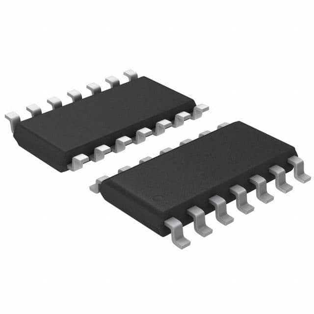
Package
The 74F14SCX is available in a small outline integrated circuit (SOIC) package. This package offers excellent thermal performance and ease of handling during assembly.
Essence
The essence of the 74F14SCX lies in its ability to provide reliable and stable digital signal processing, ensuring accurate data transmission and minimizing errors caused by noise or signal distortions.
Packaging/Quantity
The 74F14SCX is typically packaged in reels or tubes, containing a quantity of 250 or 1000 units per package, respectively.
Specifications
- Supply Voltage Range: 4.5V to 5.5V
- Input Voltage Range: 0V to Vcc
- Output Voltage Range: 0V to Vcc
- Operating Temperature Range: -40°C to +85°C
- Propagation Delay Time: 6 ns (max)
- Input Capacitance: 3 pF (typ)
- Output Drive Capability: 10 TTL loads
Detailed Pin Configuration
The 74F14SCX consists of 14 pins arranged as follows:
__    __
   A1 | 1  14 | Vcc
   B1 | 2  13 | A2
   A2 | 3  12 | B2
   Y1 | 4  11 | A3
   B2 | 5  10 | Y2
   Y2 | 6   9 | B3
  GND | 7   8 | Y3
       --------
Functional Features
- Schmitt trigger inputs: The 74F14SCX incorporates Schmitt trigger inputs, which provide hysteresis and improve noise immunity. This ensures reliable operation even in the presence of noisy or distorted input signals.
- Inverting function: The device acts as an inverter, producing an inverted output signal compared to its input.
- High-speed operation: With a propagation delay time of only 6 ns, the 74F14SCX is capable of processing digital signals at high speeds.
Advantages and Disadvantages
Advantages
- Excellent noise immunity due to Schmitt trigger inputs
- Fast response time
- Wide operating voltage range allows compatibility with various systems
- Low power consumption for energy-efficient applications
- Compact package size enables space-saving designs
Disadvantages
- Limited output drive capability compared to some other ICs
- Not suitable for analog signal processing applications
Working Principles
The 74F14SCX utilizes Schmitt trigger inputs to convert analog input signals into digital outputs. When the input voltage crosses predefined threshold levels, the output switches between logic high and logic low states. This hysteresis property ensures that the output remains stable even in the presence of noise or signal distortions.
Detailed Application Field Plans
The 74F14SCX finds extensive use in various digital electronics applications, including: - Signal conditioning in communication systems - Noise filtering in audio circuits - Waveform shaping in data transmission - Clock synchronization in microcontrollers - Pulse generation in timing circuits
Detailed and Complete Alternative Models
- 74HC14: Similar functionality with a wider supply voltage range
- CD40106: Comparable Schmitt trigger inverter with higher output drive capability
- SN74LS14: Equivalent IC with TTL-compatible inputs and outputs
These alternative models can be used as substitutes for the 74F14SCX, depending on specific application requirements.
In conclusion, the 74F14SCX is a versatile integrated circuit that provides reliable signal conditioning and waveform shaping capabilities. Its Schmitt trigger inputs, high-speed operation, and compact package make it suitable for a wide range of digital electronics applications.
Enumere 10 preguntas y respuestas comunes relacionadas con la aplicación de 74F14SCX en soluciones técnicas
Sure! Here are 10 common questions and answers related to the application of 74F14SCX in technical solutions:
Q: What is the 74F14SCX? A: The 74F14SCX is a hex inverter with Schmitt-trigger inputs, which means it can convert low-level signals into high-level signals and vice versa.
Q: What are the typical applications of the 74F14SCX? A: The 74F14SCX is commonly used in digital circuits for signal conditioning, noise filtering, waveform shaping, and level shifting.
Q: How many inverters are there in a 74F14SCX? A: The 74F14SCX contains six independent inverters, making it suitable for various applications that require multiple signal conversions.
Q: What is the operating voltage range of the 74F14SCX? A: The 74F14SCX operates within a voltage range of 4.5V to 5.5V, which makes it compatible with standard TTL logic levels.
Q: Can the 74F14SCX be used with CMOS logic? A: Yes, the 74F14SCX can be used with CMOS logic as long as proper voltage level translation is implemented between the two logic families.
Q: Does the 74F14SCX have built-in protection against electrostatic discharge (ESD)? A: No, the 74F14SCX does not have built-in ESD protection. It is recommended to follow proper ESD handling procedures during installation and usage.
Q: What is the maximum frequency at which the 74F14SCX can operate? A: The 74F14SCX has a maximum operating frequency of around 100 MHz, making it suitable for most digital applications.
Q: Can the 74F14SCX drive capacitive loads directly? A: The 74F14SCX can drive small capacitive loads directly, but for larger capacitive loads, it is recommended to use additional buffering or level-shifting components.
Q: What is the power consumption of the 74F14SCX? A: The power consumption of the 74F14SCX depends on the operating frequency and load conditions. It typically consumes around 10-20 mW per gate.
Q: Are there any specific layout considerations when using the 74F14SCX? A: Yes, it is important to follow good PCB layout practices, such as minimizing trace lengths, providing proper decoupling capacitors, and avoiding noise coupling between traces, to ensure optimal performance of the 74F14SCX.
Please note that these answers are general and may vary depending on specific application requirements.