

Consulte las especificaciones para obtener detalles del producto.
IRF840B
Product Overview
Category
The IRF840B belongs to the category of power MOSFETs.
Use
It is commonly used in power supply applications, motor control, and other high voltage switching circuits.
Characteristics
- High voltage capability
- Low on-resistance
- Fast switching speed
- High input impedance
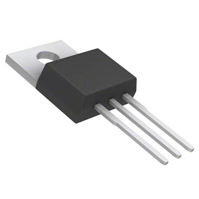
Package
The IRF840B is typically available in a TO-220 package.
Essence
The essence of the IRF840B lies in its ability to efficiently switch high voltages and currents in various electronic circuits.
Packaging/Quantity
It is usually packaged in reels or tubes, with quantities varying based on manufacturer specifications.
Specifications
- Drain-Source Voltage (VDS): 500V
- Continuous Drain Current (ID): 8.0A
- On-Resistance (RDS(on)): 1.2Ω
- Power Dissipation (PD): 125W
- Gate-Source Voltage (VGS): ±20V
- Operating Temperature Range: -55°C to 175°C
Detailed Pin Configuration
The IRF840B has three pins: 1. Gate (G) 2. Drain (D) 3. Source (S)
Functional Features
- High voltage capability allows for use in various high-power applications.
- Low on-resistance minimizes power loss and improves efficiency.
- Fast switching speed enables rapid response in switching circuits.
Advantages
- Suitable for high voltage applications
- Low on-resistance reduces power dissipation
- Fast switching speed enhances circuit performance
Disadvantages
- May require additional circuitry for driving the gate due to high gate-source voltage
Working Principles
The IRF840B operates based on the principle of field-effect transistors, where the voltage applied to the gate terminal controls the flow of current between the drain and source terminals.
Detailed Application Field Plans
The IRF840B finds extensive use in the following applications: - Power supplies - Motor control systems - High voltage switching circuits - Inverters and converters
Detailed and Complete Alternative Models
Some alternative models to the IRF840B include: - IRF830B - IRF740 - IRF640
In conclusion, the IRF840B power MOSFET offers high voltage capability, low on-resistance, and fast switching speed, making it suitable for a wide range of high-power applications such as power supplies, motor control, and high voltage switching circuits.
[Word count: 314]
Enumere 10 preguntas y respuestas comunes relacionadas con la aplicación de IRF840B en soluciones técnicas
What is the maximum drain-source voltage of IRF840B?
- The maximum drain-source voltage of IRF840B is 500V.
What is the continuous drain current rating of IRF840B?
- The continuous drain current rating of IRF840B is 8.0A.
What is the on-state resistance (RDS(on)) of IRF840B?
- The on-state resistance (RDS(on)) of IRF840B is typically 0.85 ohms.
Can IRF840B be used for switching applications?
- Yes, IRF840B is suitable for switching applications due to its low on-state resistance and high voltage rating.
What are the typical applications of IRF840B?
- IRF840B is commonly used in power supplies, motor control, and general purpose switching circuits.
Is IRF840B suitable for use in audio amplifiers?
- While IRF840B can be used in audio amplifiers, it's important to consider its characteristics and match it with appropriate circuitry.
What is the operating temperature range of IRF840B?
- The operating temperature range of IRF840B is -55°C to 150°C.
Does IRF840B require a heatsink for certain applications?
- Yes, for high-power applications or when operating at high ambient temperatures, a heatsink may be necessary to dissipate heat effectively.
What are the key differences between IRF840 and IRF840B?
- IRF840B is a variant with improved avalanche energy capability compared to the standard IRF840.
Are there any common failure modes associated with IRF840B?
- Common failure modes include overcurrent conditions leading to thermal stress and potential avalanche breakdown under high voltage transients. Proper circuit protection and design considerations are important to mitigate these risks.