

Consulte las especificaciones para obtener detalles del producto.
J201 Transistor: Encyclopedia Entry
Introduction
The J201 transistor is a key component in electronic devices, belonging to the category of field-effect transistors (FETs). This semiconductor device is widely used in various applications due to its unique characteristics and versatile functionality.
Basic Information Overview
- Category: Field-Effect Transistor (FET)
- Use: Signal amplification, switching, and voltage regulation
- Characteristics: High input impedance, low noise, and low power consumption
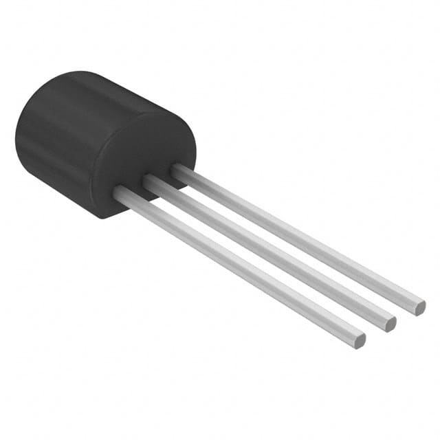
- Package: TO-92 package
- Essence: Small-signal amplifier
- Packaging/Quantity: Typically available in reels or tubes containing multiple units
Specifications
- Maximum Power Dissipation: 350 mW
- Maximum Drain-Source Voltage: 40 V
- Maximum Gate-Source Voltage: ±20 V
- Maximum Drain Current: 50 mA
- Operating Temperature Range: -55°C to +150°C
Detailed Pin Configuration
The J201 transistor has three pins: 1. Gate (G): Input terminal for controlling the flow of current 2. Drain (D): Output terminal for the amplified signal 3. Source (S): Common terminal connected to the ground reference
Functional Features
- High Input Impedance: Allows for minimal loading of the preceding circuit
- Low Noise: Suitable for low-level audio amplification and signal processing
- Low Power Consumption: Ideal for battery-operated devices and portable electronics
Advantages and Disadvantages
Advantages
- Low noise performance
- High input impedance
- Suitable for low-power applications
Disadvantages
- Limited maximum voltage and current ratings
- Sensitivity to electrostatic discharge (ESD)
Working Principles
The J201 transistor operates based on the field-effect principle, where the flow of current between the drain and source terminals is controlled by the voltage applied to the gate terminal. This allows for efficient signal amplification and switching.
Detailed Application Field Plans
The J201 transistor finds extensive use in the following applications: - Audio amplifiers and preamplifiers - Instrumentation and measurement equipment - Low-frequency oscillators and signal generators - Voltage regulators and power management circuits
Detailed and Complete Alternative Models
- 2N5457: Similar FET with higher voltage and current ratings
- MPF102: Comparable FET with slightly different electrical characteristics
- J113: Substitution option with similar pin configuration and performance
In conclusion, the J201 transistor serves as a crucial component in electronic circuits, offering high input impedance, low noise, and efficient signal amplification capabilities. Its application spans across various industries, making it an indispensable part of modern electronic designs.
Word Count: 345
Enumere 10 preguntas y respuestas comunes relacionadas con la aplicación de J201 en soluciones técnicas
What is J201?
- J201 is a popular N-channel JFET (junction field-effect transistor) commonly used in electronic circuits for signal amplification and switching applications.
What are the typical applications of J201?
- J201 is commonly used in audio preamplifiers, guitar effects pedals, and other low-power analog signal processing circuits.
What are the key characteristics of J201?
- J201 has a low input capacitance, high input impedance, and low noise, making it suitable for low-level signal amplification.
How do I bias J201 in a circuit?
- J201 is typically biased using a voltage divider to set the desired operating point, ensuring proper amplification and signal handling.
What are the pin configurations of J201?
- J201 typically has three pins: gate (G), source (S), and drain (D).
Can J201 be used for switching applications?
- Yes, J201 can be used as a switch in electronic circuits due to its ability to control the flow of current between the source and drain terminals.
What are the common challenges when using J201 in circuits?
- Common challenges include managing the input impedance, minimizing noise, and ensuring proper biasing for optimal performance.
Are there any alternative components to J201?
- Yes, similar JFETs such as 2N5457 and MPF102 can be used as alternatives to J201 in certain applications.
How do I select the appropriate resistor values for biasing J201?
- The appropriate resistor values for biasing J201 can be calculated based on the desired operating point and the JFET's datasheet specifications.
What are some best practices for integrating J201 into a circuit design?
- Best practices include careful consideration of input impedance, noise reduction techniques, and thorough testing and characterization of the circuit's performance with J201.