

Consulte las especificaciones para obtener detalles del producto.
KSC2518R Product Overview
Introduction
The KSC2518R is a versatile electronic component that belongs to the category of semiconductor devices. This entry provides an in-depth overview of the product, including its basic information, specifications, detailed pin configuration, functional features, advantages and disadvantages, working principles, application field plans, and alternative models.
Basic Information Overview
- Category: Semiconductor Device
- Use: Amplification and Switching Applications
- Characteristics: High Gain, Low Noise, Small Signal Amplification
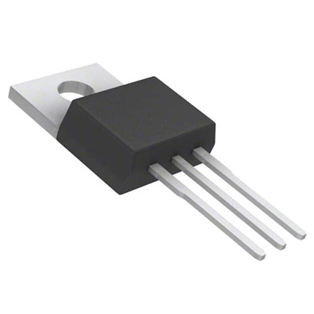
- Package: TO-92 Package
- Essence: Bipolar Junction Transistor (BJT)
- Packaging/Quantity: Typically available in reels or tubes containing multiple units
Specifications
- Maximum Collector-Emitter Voltage: 40V
- Maximum Collector Current: 600mA
- DC Current Gain (hFE): 100 - 300
- Power Dissipation: 625mW
- Operating Temperature Range: -55°C to 150°C
Detailed Pin Configuration
The KSC2518R typically consists of three pins: 1. Emitter (E): Connected to the N-type material 2. Base (B): Controls the transistor action 3. Collector (C): Connected to the P-type material
Functional Features
- High gain amplification for small signals
- Low noise operation
- Suitable for audio amplification and switching applications
- Compact TO-92 package for easy integration into circuit designs
Advantages and Disadvantages
Advantages
- High gain allows for effective signal amplification
- Low noise operation ensures clear signal processing
- Versatile applications in audio amplification and switching circuits
Disadvantages
- Limited power handling capabilities compared to power transistors
- Sensitive to temperature variations
Working Principles
The KSC2518R operates based on the principles of bipolar junction transistors. When a small current flows into the base terminal, it controls a larger current flow between the collector and emitter terminals, allowing for signal amplification and switching functions.
Detailed Application Field Plans
The KSC2518R finds extensive use in various electronic applications, including: - Audio amplifiers - Signal processing circuits - Switching circuits - Oscillator circuits - Voltage regulators
Detailed and Complete Alternative Models
Some alternative models to the KSC2518R include: - 2N3904 - BC547 - 2N2222 - PN2222
In conclusion, the KSC2518R offers high gain amplification and low noise operation, making it suitable for a wide range of small signal amplification and switching applications. Its compact package and versatile characteristics make it a popular choice among electronics designers.
Word Count: 410
Enumere 10 preguntas y respuestas comunes relacionadas con la aplicación de KSC2518R en soluciones técnicas
What is KSC2518R?
- KSC2518R is a high-voltage switching transistor commonly used in electronic circuits for various technical applications.
What are the key features of KSC2518R?
- The KSC2518R features high voltage capability, low saturation voltage, and high current gain, making it suitable for power management and switching applications.
What are the typical applications of KSC2518R?
- KSC2518R is often used in power supply circuits, LED driver circuits, motor control, and other high-voltage switching applications.
What is the maximum voltage and current ratings for KSC2518R?
- The maximum collector-emitter voltage (VCEO) is typically around 400V, and the maximum collector current (IC) is around 1A.
How does KSC2518R compare to similar transistors in its class?
- Compared to similar transistors, KSC2518R offers lower saturation voltage and higher current gain, making it suitable for high-efficiency power management solutions.
What are the recommended operating conditions for KSC2518R?
- It is recommended to operate KSC2518R within a specified temperature range and to ensure proper heat dissipation to maintain its performance and reliability.
Are there any specific considerations for driving KSC2518R in a circuit?
- Proper base drive voltage and current should be provided to ensure efficient switching and to avoid thermal stress on the transistor.
Can KSC2518R be used in audio amplifier circuits?
- While KSC2518R is primarily designed for power management and switching applications, it may not be the most suitable choice for audio amplifier circuits due to its specific characteristics.
What are the common failure modes of KSC2518R?
- Common failure modes include thermal overstress, overvoltage spikes, and excessive current leading to breakdown or degradation of the transistor.
Where can I find detailed application notes and reference designs for using KSC2518R in technical solutions?
- Detailed application notes and reference designs for KSC2518R can often be found in the manufacturer's datasheets, application guides, and technical support resources. Additionally, online forums and communities dedicated to electronics may provide valuable insights and practical examples of KSC2518R usage in technical solutions.