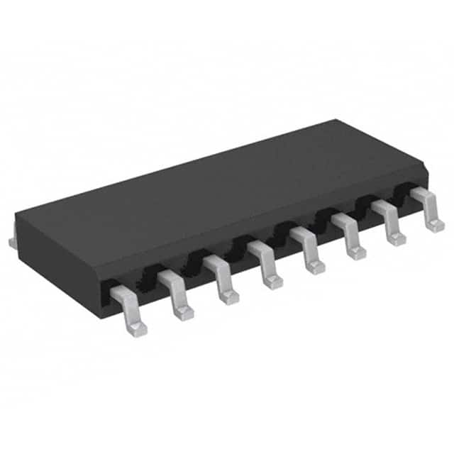
Consulte las especificaciones para obtener detalles del producto.

MC14555BDG
Product Overview
- Category: Integrated Circuit
- Use: Digital Multiplexer/Demultiplexer
- Characteristics: High-speed, low-power consumption
- Package: SOIC-16
- Essence: A versatile digital IC used for multiplexing and demultiplexing signals.
- Packaging/Quantity: Available in reels of 2500 units.
Specifications
- Supply Voltage: 3V to 18V
- Input Voltage: 0V to VDD
- Output Voltage: 0V to VDD
- Operating Temperature Range: -40°C to +85°C
- Maximum Propagation Delay: 200ns
Detailed Pin Configuration
The MC14555BDG has a total of 16 pins. The pin configuration is as follows:
- Pin 1: Select Input S0
- Pin 2: Select Input S1
- Pin 3: Enable Input E
- Pin 4: Data Input D0
- Pin 5: Data Input D1
- Pin 6: Data Input D2
- Pin 7: Data Input D3
- Pin 8: Data Output Q0
- Pin 9: Data Output Q1
- Pin 10: Data Output Q2
- Pin 11: Data Output Q3
- Pin 12: Ground (GND)
- Pin 13: Data Output Q4
- Pin 14: Data Output Q5
- Pin 15: Data Output Q6
- Pin 16: Data Output Q7
Functional Features
- Can be used as an 8-channel multiplexer or demultiplexer.
- Low power consumption makes it suitable for battery-powered devices.
- High-speed operation allows for efficient signal processing.
- Wide operating voltage range provides flexibility in various applications.
Advantages and Disadvantages
Advantages
- Versatile functionality as both a multiplexer and demultiplexer.
- Low power consumption extends battery life.
- High-speed operation enables efficient signal handling.
- Wide operating voltage range enhances compatibility.
Disadvantages
- Limited number of input/output channels compared to other ICs.
- Propagation delay may affect real-time applications with strict timing requirements.
Working Principles
The MC14555BDG is based on the principle of digital multiplexing and demultiplexing. It uses select inputs (S0, S1) to determine the desired channel for data input (D0-D3) and output (Q0-Q7). The enable input (E) controls the operation of the IC. When enabled, the selected data input is routed to the corresponding data output. The IC operates within the specified voltage range and has a maximum propagation delay of 200ns.
Detailed Application Field Plans
The MC14555BDG finds applications in various fields, including:
- Communication Systems: Used for signal routing and switching in telecommunication networks.
- Data Acquisition: Enables multiplexing of analog signals for data acquisition systems.
- Industrial Automation: Facilitates control signal routing in industrial automation processes.
- Test and Measurement: Allows for efficient signal routing and selection in test equipment.
- Audio/Video Switching: Used in audio/video systems for channel selection and routing.
Detailed and Complete Alternative Models
- CD4051B: 8-channel analog multiplexer/demultiplexer IC.
- SN74HC151: 8-input multiplexer IC.
- CD74HC4067: 16-channel analog multiplexer/demultiplexer IC.
- 74HC138: 3-to-8 line decoder/demultiplexer IC.
These alternative models offer similar functionality and can be considered as alternatives to the MC14555BDG based on specific application requirements.
Word Count: 442 words
Enumere 10 preguntas y respuestas comunes relacionadas con la aplicación de MC14555BDG en soluciones técnicas
Sure! Here are 10 common questions and answers related to the application of MC14555BDG in technical solutions:
Q: What is MC14555BDG? A: MC14555BDG is a CMOS dual BCD counter IC (Integrated Circuit) commonly used in digital applications.
Q: What is the operating voltage range for MC14555BDG? A: The operating voltage range for MC14555BDG is typically between 3V and 18V.
Q: Can MC14555BDG be used as a frequency divider? A: Yes, MC14555BDG can be used as a frequency divider by connecting the appropriate input and output pins.
Q: How many counters are there in MC14555BDG? A: MC14555BDG consists of two independent BCD counters, each with separate clock inputs and outputs.
Q: What is the maximum clock frequency for MC14555BDG? A: The maximum clock frequency for MC14555BDG is typically around 6 MHz.
Q: Can MC14555BDG be used in low-power applications? A: Yes, MC14555BDG is designed to operate at low power and has a low quiescent current consumption.
Q: What is the purpose of the reset pin in MC14555BDG? A: The reset pin in MC14555BDG is used to clear the counter and set it to its initial state.
Q: Can MC14555BDG be cascaded to increase the counting range? A: Yes, multiple MC14555BDG ICs can be cascaded together to increase the counting range.
Q: Is MC14555BDG suitable for driving LED displays? A: Yes, MC14555BDG can be used to drive LED displays by connecting the appropriate output pins to the display segments.
Q: Are there any specific precautions to consider when using MC14555BDG? A: It is important to ensure that the power supply voltage does not exceed the specified maximum limit and to follow the recommended operating conditions mentioned in the datasheet.
Please note that these answers are general and may vary depending on the specific application and requirements. Always refer to the datasheet and consult with technical experts for accurate information.

