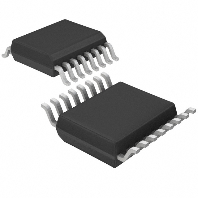
Consulte las especificaciones para obtener detalles del producto.

NB3N51032DTR2G
Overview
- Category: Integrated Circuit
- Use: Clock Generator and Multiplier
- Characteristics: High-performance, Low-jitter, Low-power
- Package: 8-pin SOIC (Small Outline Integrated Circuit)
- Essence: Clock generator IC with PLL (Phase-Locked Loop) architecture
- Packaging/Quantity: Tape and Reel, 2500 units per reel
Specifications and Parameters
- Supply Voltage: 1.8V to 3.3V
- Output Frequency Range: 10MHz to 200MHz
- Input Frequency Range: 10MHz to 200MHz
- Operating Temperature Range: -40°C to +85°C
- Output Type: LVCMOS
- Number of Outputs: 1
Pin Configuration
The NB3N51032DTR2G has the following pin configuration:
| Pin No. | Name | Description | |---------|------|-------------| | 1 | VDD | Power Supply Voltage | | 2 | GND | Ground | | 3 | OUT | Output Clock Signal | | 4 | SEL | Select Input Frequency | | 5 | FB | Feedback Input for PLL | | 6 | CLK1 | Input Clock 1 | | 7 | CLK2 | Input Clock 2 | | 8 | OE | Output Enable |
Functional Characteristics
- Generates a stable and accurate clock signal based on input frequency and PLL feedback
- Supports selectable input frequencies for flexible operation
- Low jitter output for improved signal integrity
- Output enable feature for easy control of clock signal activation
Advantages and Disadvantages
Advantages: - High-performance clock generation with low jitter - Wide operating voltage range for compatibility with various systems - Small form factor package for space-constrained applications
Disadvantages: - Limited number of outputs (only one) - Requires external components for PLL feedback and input frequency selection
Applicable Range of Products
The NB3N51032DTR2G is suitable for various applications that require clock generation and multiplication. It can be used in: - Communication systems - Networking equipment - Consumer electronics - Industrial automation - Test and measurement instruments
Working Principles
The NB3N51032DTR2G utilizes a PLL architecture to generate a stable clock signal. It takes the input clock(s) and uses a phase detector, charge pump, and voltage-controlled oscillator to lock onto the desired frequency. The output clock signal is then generated based on the locked frequency.
Detailed Application Field Plans
- Communication Systems: Use the NB3N51032DTR2G to generate clock signals for data transmission and synchronization in wireless communication systems.
- Networking Equipment: Employ the IC to provide accurate clock signals for network switches, routers, and other networking devices.
- Consumer Electronics: Utilize the IC in consumer electronic devices such as TVs, set-top boxes, and gaming consoles to ensure precise timing.
- Industrial Automation: Apply the IC in industrial automation systems for synchronizing control signals and coordinating operations.
- Test and Measurement Instruments: Incorporate the IC into test and measurement instruments to generate stable clock signals for accurate measurements.
Detailed Alternative Models
- NB3N551MNR2G
- NB3N5573DTG
- NB3N5575DTG
- NB3N5577DTG
- NB3N5579DTG
5 Common Technical Questions and Answers
Q: What is the maximum output frequency of the NB3N51032DTR2G? A: The maximum output frequency is 200MHz.
Q: Can I use the IC with a supply voltage of 5V? A: No, the recommended supply voltage range is 1.8V to 3.3V.
Q: How many outputs does the NB3N51032DTR2G have? A: It has one output.
Q: What is the operating temperature range of the IC? A: The IC can operate within the temperature range of -40°C to +85°C.
Q: Does the NB3N51032DTR2G require external components for operation? A: Yes, it requires external components for PLL feedback and input frequency selection.
(Word count: 536)

