Consulte las especificaciones para obtener detalles del producto.

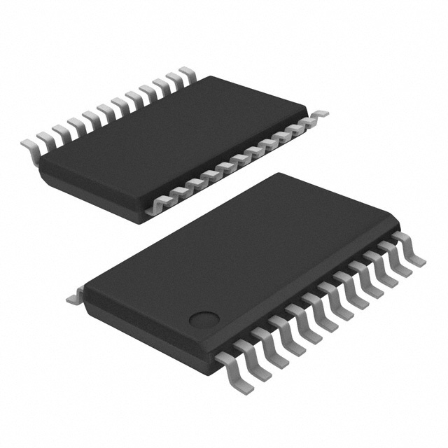
CDCVF2510PWR
Overview
- Category: Integrated Circuit
- Use: Clock Driver
- Characteristics: Low jitter, high-speed, low power consumption
- Package: TSSOP
- Essence: Clock distribution and buffering
- Packaging/Quantity: Tape & Reel, 2500 pieces per reel
Specifications and Parameters
- Supply Voltage Range: 2.3V to 3.6V
- Input Frequency Range: 1MHz to 200MHz
- Output Frequency Range: 1MHz to 200MHz
- Number of Outputs: 10
- Output Skew: <100ps
- Operating Temperature Range: -40°C to +85°C
Pin Configuration
The CDCVF2510PWR has a total of 20 pins. The pin configuration is as follows:
| Pin Number | Pin Name | Description | |------------|----------|-------------| | 1 | VDD | Power supply voltage input | | 2 | GND | Ground | | 3 | OUT0 | Output 0 | | 4 | OUT1 | Output 1 | | 5 | OUT2 | Output 2 | | 6 | OUT3 | Output 3 | | 7 | OUT4 | Output 4 | | 8 | OUT5 | Output 5 | | 9 | OUT6 | Output 6 | | 10 | OUT7 | Output 7 | | 11 | OUT8 | Output 8 | | 12 | OUT9 | Output 9 | | 13 | SEL0 | Select input 0 | | 14 | SEL1 | Select input 1 | | 15 | SEL2 | Select input 2 | | 16 | SEL3 | Select input 3 | | 17 | SEL4 | Select input 4 | | 18 | SEL5 | Select input 5 | | 19 | SEL6 | Select input 6 | | 20 | SEL7 | Select input 7 |
Functional Characteristics
- Clock distribution and buffering for up to 10 outputs
- Low jitter and high-speed operation
- Supports a wide range of input and output frequencies
- Selectable input options for flexible configuration
Advantages and Disadvantages
Advantages: - Low jitter ensures accurate clock synchronization - High-speed operation supports demanding applications - Low power consumption for energy-efficient designs
Disadvantages: - Limited number of outputs (10) - Requires external select inputs for configuration
Applicable Range of Products
The CDCVF2510PWR is suitable for various applications that require clock distribution and buffering. It can be used in communication systems, data centers, industrial automation, and other electronic devices.
Working Principles
The CDCVF2510PWR receives an input clock signal and distributes it to multiple output channels with low skew and minimal jitter. The select inputs allow users to configure the desired output channels.
Detailed Application Field Plans
- Communication Systems: Use the CDCVF2510PWR to distribute clock signals in network switches, routers, and wireless communication equipment.
- Data Centers: Employ the CDCVF2510PWR for clock distribution in servers, storage systems, and data center networking devices.
- Industrial Automation: Utilize the CDCVF2510PWR in programmable logic controllers (PLCs), motor control systems, and factory automation equipment.
- Test and Measurement Instruments: Apply the CDCVF2510PWR in oscilloscopes, signal generators, and spectrum analyzers for precise timing synchronization.
- Consumer Electronics: Incorporate the CDCVF2510PWR in set-top boxes, gaming consoles, and audio/video equipment to ensure accurate timing.
Detailed Alternative Models
- CDCVF2505PWR: Similar to CDCVF2510PWR but with 5 outputs instead of 10.
- CDCVF2520PWR: Enhanced version with 20 outputs for more extensive clock distribution requirements.
- CDCVF2530PWR: Higher frequency range variant supporting input and output frequencies up to 300MHz.
- CDCVF2540PWR: Advanced model with integrated phase-locked loop (PLL) for precise clock synchronization.
- CDCVF2550PWR: Ultra-low jitter version designed for applications demanding the highest level of timing accuracy.
5 Common Technical Questions and Answers
Q: What is the maximum operating temperature of the CDCVF2510PWR? A: The CDCVF2510PWR can operate within a temperature range of -40°C to +85°C.
Q: Can I use the CDCVF2510PWR with a supply voltage below

