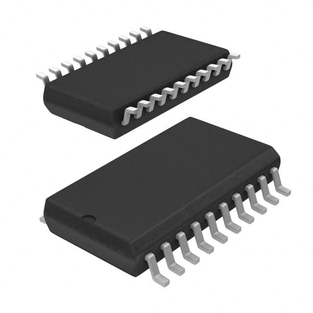
Consulte las especificaciones para obtener detalles del producto.

SN74ALS621ADWR
Product Overview
- Category: Integrated Circuit (IC)
- Use: Logic Gate
- Characteristics: Advanced Schottky (ALS) technology, 4-bit bus transceiver with 3-state outputs
- Package: SOIC (Small Outline Integrated Circuit)
- Essence: High-speed and low-power consumption logic gate
- Packaging/Quantity: Tape and Reel, 2500 units per reel
Specifications
- Supply Voltage Range: 4.5V to 5.5V
- Input Voltage Range: 0V to VCC
- Output Voltage Range: 0V to VCC
- Operating Temperature Range: -40°C to +85°C
- Propagation Delay Time: 6ns (typical)
- Output Current: ±24mA
- Input Capacitance: 4pF
- Output Capacitance: 8pF
Detailed Pin Configuration
The SN74ALS621ADWR has a total of 20 pins arranged as follows:
- A1 (Input A1)
- B1 (Input B1)
- G1 (Output Enable Input for Port A)
- OE (Output Enable Input for Port B)
- A2 (Input A2)
- B2 (Input B2)
- G2 (Output Enable Input for Port A)
- VCC (Positive Power Supply)
- B3 (Input B3)
- A3 (Input A3)
- G3 (Output Enable Input for Port B)
- GND (Ground)
- Y3 (Output Y3)
- Y2 (Output Y2)
- Y1 (Output Y1)
- A4 (Input A4)
- B4 (Input B4)
- G4 (Output Enable Input for Port B)
- NC (No Connection)
- VCC (Positive Power Supply)
Functional Features
- 4-bit bidirectional bus transceiver
- Non-inverting outputs
- 3-state outputs for bus-oriented applications
- High-speed operation with minimal power consumption
- TTL-compatible inputs and outputs
- Schmitt-trigger input on all inputs
- ESD protection exceeds 2000V per MIL-STD-883C, Method 3015.2
Advantages and Disadvantages
Advantages: - High-speed operation allows for efficient data transfer - Low power consumption helps in reducing energy usage - Schmitt-trigger input ensures noise immunity - ESD protection provides reliability in harsh environments
Disadvantages: - Limited to 4-bit bus transceiver functionality - Requires external pull-up resistors for proper operation
Working Principles
The SN74ALS621ADWR is a 4-bit bus transceiver that enables bidirectional data transfer between two buses. It operates by using the control signals G1 and G2 to enable the outputs Y1, Y2, Y3, and Y4. When G1 is high and G2 is low, data from Port A is transferred to Port B. Conversely, when G1 is low and G2 is high, data from Port B is transferred to Port A. The outputs are put in a high-impedance state when either G1 or G2 is low.
Detailed Application Field Plans
The SN74ALS621ADWR is commonly used in various applications, including:
- Data communication systems
- Microprocessor-based systems
- Industrial control systems
- Automotive electronics
- Test and measurement equipment
Detailed and Complete Alternative Models
- SN74ALS623ADWR: Similar to SN74ALS621ADWR but with inverted outputs
- SN74ALS620ADWR: 4-bit bus transceiver with non-inverting outputs and active-high enable inputs
- SN74ALS622ADWR: 4-bit bus transceiver with inverted outputs and active-low enable inputs
These alternative models provide similar functionality to the SN74ALS621ADWR but may have slight variations in characteristics or pin configuration.
Word count: 456 words
Enumere 10 preguntas y respuestas comunes relacionadas con la aplicación de SN74ALS621ADWR en soluciones técnicas
Sure! Here are 10 common questions and answers related to the application of SN74ALS621ADWR:
Q: What is SN74ALS621ADWR? A: SN74ALS621ADWR is a specific type of integrated circuit (IC) commonly used in technical solutions for data bus buffering and latching.
Q: What is the purpose of SN74ALS621ADWR? A: The purpose of this IC is to provide buffering and latching capabilities for data buses, ensuring reliable communication between different components in a system.
Q: What voltage levels does SN74ALS621ADWR support? A: SN74ALS621ADWR supports a wide range of voltage levels, typically from 2V to 6V.
Q: How many data lines can SN74ALS621ADWR handle? A: This IC can handle up to 8 data lines, making it suitable for applications that require parallel data transfer.
Q: Can SN74ALS621ADWR be used in both input and output modes? A: Yes, SN74ALS621ADWR can be used in both input and output modes, allowing bidirectional data flow.
Q: Does SN74ALS621ADWR have any built-in error detection or correction features? A: No, SN74ALS621ADWR does not have any built-in error detection or correction features. It primarily focuses on data buffering and latching.
Q: What is the maximum operating frequency of SN74ALS621ADWR? A: The maximum operating frequency of SN74ALS621ADWR is typically around 25 MHz, but it may vary depending on the specific application.
Q: Can SN74ALS621ADWR be cascaded to increase the number of data lines? A: Yes, SN74ALS621ADWR can be cascaded to increase the number of data lines by connecting multiple ICs together.
Q: What is the power supply requirement for SN74ALS621ADWR? A: SN74ALS621ADWR typically requires a single power supply voltage in the range of 4.5V to 5.5V.
Q: Are there any specific precautions to consider when using SN74ALS621ADWR? A: It is important to ensure proper decoupling and bypass capacitors are used near the power supply pins of SN74ALS621ADWR to minimize noise and voltage fluctuations.
Please note that these answers are general and may vary depending on the specific application and datasheet of SN74ALS621ADWR.

