Consulte las especificaciones para obtener detalles del producto.

SN74AS652DWR
Product Overview
Category
SN74AS652DWR belongs to the category of integrated circuits (ICs).
Use
This product is commonly used in electronic devices for data bus multiplexing and demultiplexing applications.
Characteristics
- High-speed operation
- Wide operating voltage range
- Low power consumption
- Compatibility with TTL logic levels
- 3-state outputs
- Schmitt-trigger inputs
Package
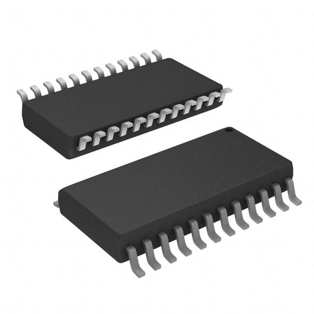
SN74AS652DWR is available in a standard SOIC (Small Outline Integrated Circuit) package.
Essence
The essence of SN74AS652DWR lies in its ability to efficiently multiplex and demultiplex data signals in electronic systems.
Packaging/Quantity
This product is typically packaged in reels, with each reel containing a specific quantity of SN74AS652DWR ICs.
Specifications
- Operating Voltage Range: 4.5V to 5.5V
- Input Voltage Range: 0V to VCC
- Output Voltage Range: 0V to VCC
- Operating Temperature Range: -40°C to +85°C
- Number of Channels: 8
- Logic Family: AS
- Logic Type: Bipolar
- Output Type: 3-State
- Package Type: SOIC
- Package Size: 20-pin
Detailed Pin Configuration
- A0 - Multiplexer Address Input 0
- A1 - Multiplexer Address Input 1
- A2 - Multiplexer Address Input 2
- A3 - Multiplexer Address Input 3
- A4 - Multiplexer Address Input 4
- A5 - Multiplexer Address Input 5
- A6 - Multiplexer Address Input 6
- A7 - Multiplexer Address Input 7
- OE - Output Enable Input
- I/O0 - Data Input/Output 0
- I/O1 - Data Input/Output 1
- I/O2 - Data Input/Output 2
- I/O3 - Data Input/Output 3
- I/O4 - Data Input/Output 4
- I/O5 - Data Input/Output 5
- I/O6 - Data Input/Output 6
- I/O7 - Data Input/Output 7
- GND - Ground
- VCC - Power Supply
- NC - No Connection
Functional Features
- Multiplexes and demultiplexes data signals efficiently
- Allows selection of desired input/output channels using address inputs
- Enables/disables output using the output enable input
- Provides 3-state outputs for bus sharing applications
- Incorporates Schmitt-trigger inputs for noise immunity
Advantages and Disadvantages
Advantages
- High-speed operation allows for efficient data handling
- Wide operating voltage range ensures compatibility with various systems
- Low power consumption contributes to energy efficiency
- TTL logic level compatibility simplifies integration with existing circuits
- 3-state outputs facilitate bus sharing in multi-device configurations
- Schmitt-trigger inputs enhance noise immunity, improving signal integrity
Disadvantages
- Limited number of channels (8) may not be sufficient for certain applications requiring more inputs/outputs
- Availability of alternative models with additional features or different specifications may limit its suitability for specific use cases
Working Principles
SN74AS652DWR operates by receiving address inputs that determine the desired input/output channel. The selected channel's data is then either multiplexed onto a single output line or demultiplexed from a single input line to the corresponding output channel. The output enable input controls whether the outputs are enabled or disabled. The 3-state outputs allow multiple devices to share a common bus without interference.
Detailed Application Field Plans
SN74AS652DWR finds applications in various fields, including: 1. Data communication systems 2. Industrial automation 3. Automotive electronics 4. Medical equipment 5. Consumer electronics 6. Telecommunications 7. Robotics 8. Instrumentation and measurement devices
Detailed and Complete Alternative Models
- SN74AS651DWR - Similar to SN74AS652DWR but with 4 channels instead of 8.
- SN74AS653DWR - Similar to SN74AS652DWR but with inverted outputs.
- SN74AS654DWR - Similar to SN74AS652DWR but with additional output enable inputs for individual channel control.
These alternative models provide flexibility in terms of channel count and output control options, catering to different application requirements.
Word count: 550 words
Enumere 10 preguntas y respuestas comunes relacionadas con la aplicación de SN74AS652DWR en soluciones técnicas
Sure! Here are 10 common questions and answers related to the application of SN74AS652DWR in technical solutions:
Q: What is SN74AS652DWR? A: SN74AS652DWR is a type of integrated circuit (IC) commonly used as a bus transceiver and register in digital systems.
Q: What is the purpose of SN74AS652DWR? A: SN74AS652DWR is designed to facilitate bidirectional data transfer between two buses with different voltage levels or protocols.
Q: What voltage levels does SN74AS652DWR support? A: SN74AS652DWR supports a wide range of voltage levels, typically from 2V to 6V.
Q: How many channels does SN74AS652DWR have? A: SN74AS652DWR has 8 bidirectional channels, allowing for simultaneous data transfer in both directions.
Q: Can SN74AS652DWR be used in both parallel and serial communication systems? A: Yes, SN74AS652DWR can be used in both parallel and serial communication systems, making it versatile for various applications.
Q: Does SN74AS652DWR require external components for operation? A: Yes, SN74AS652DWR requires external pull-up resistors and decoupling capacitors for proper operation.
Q: What is the maximum data rate supported by SN74AS652DWR? A: SN74AS652DWR can support data rates up to 40 MHz, depending on the specific operating conditions.
Q: Can SN74AS652DWR handle hot-swapping of buses? A: Yes, SN74AS652DWR is designed to support hot-swapping, allowing for seamless connection/disconnection of buses during operation.
Q: What is the power supply voltage range for SN74AS652DWR? A: SN74AS652DWR typically operates with a power supply voltage range of 4.5V to 5.5V.
Q: Are there any specific precautions to consider when using SN74AS652DWR? A: Yes, it is important to ensure proper decoupling and grounding techniques are followed to minimize noise and ensure reliable operation.
Please note that these answers are general and may vary depending on the specific application and requirements. It is always recommended to refer to the datasheet and consult the manufacturer for detailed information.

