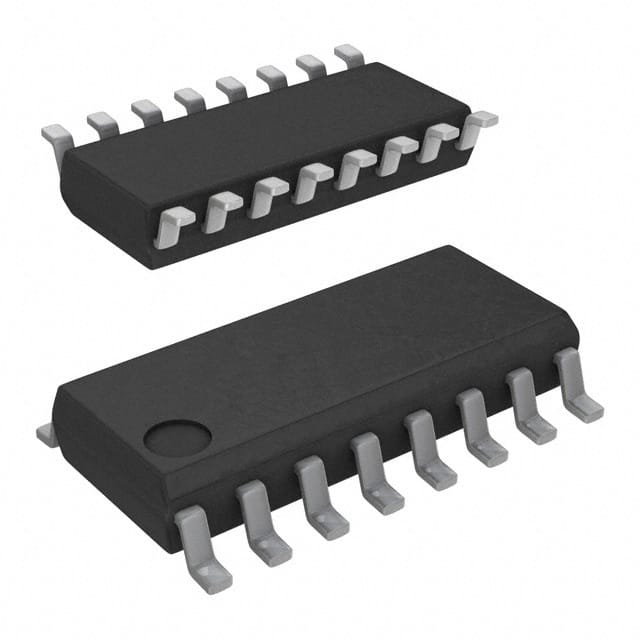
Consulte las especificaciones para obtener detalles del producto.

SN74LS251DR
Product Overview
- Category: Integrated Circuit (IC)
- Use: Data Selector/Multiplexer
- Characteristics: TTL Logic, 8-input, 1-output, active-low enable
- Package: SOIC (Small Outline Integrated Circuit)
- Essence: A versatile data selector/multiplexer IC with multiple inputs and a single output, designed for use in digital circuits.
- Packaging/Quantity: Available in reels of 2500 units or tubes of 75 units.
Specifications
- Supply Voltage: 4.75V to 5.25V
- Input Voltage: 0V to Vcc
- Output Voltage: 0V to Vcc
- Operating Temperature Range: -40°C to +85°C
- Propagation Delay Time: 9ns (typical)
- Output Current: ±8mA
- Power Dissipation: 500mW (max)
Detailed Pin Configuration
The SN74LS251DR has a total of 16 pins, which are assigned as follows:
- A0: Input A0
- A1: Input A1
- A2: Input A2
- A3: Input A3
- A4: Input A4
- A5: Input A5
- A6: Input A6
- A7: Input A7
- GND: Ground
- E: Active-Low Enable
- Y: Output
- NC: No Connection
- NC: No Connection
- Vcc: Positive Supply Voltage
- B0: Input B0
- B1: Input B1
Functional Features
- The SN74LS251DR is an 8-input data selector/multiplexer with a single output.
- It features an active-low enable input (E) that controls the operation of the device.
- The selected input is routed to the output based on the binary value applied to the address inputs (A0-A7).
- When the enable input (E) is high, all outputs are in a high-impedance state.
Advantages and Disadvantages
Advantages: - Versatile data selector/multiplexer with multiple inputs. - TTL logic ensures compatibility with various digital circuits. - Active-low enable input allows for easy control of the device. - Fast propagation delay time ensures efficient operation.
Disadvantages: - Limited to 8 inputs, may not be suitable for applications requiring more inputs. - Requires external components for proper operation. - Power dissipation can be relatively high compared to other ICs.
Working Principles
The SN74LS251DR works by selecting one of the eight inputs (B0-B1) based on the binary value applied to the address inputs (A0-A7). The active-low enable input (E) controls the operation of the device. When E is low, the selected input is routed to the output (Y), while all other inputs are disconnected from the output. When E is high, all outputs are in a high-impedance state.
Detailed Application Field Plans
The SN74LS251DR can be used in various applications, including:
- Data multiplexing: Selecting one of multiple data sources based on control signals.
- Address decoding: Routing specific addresses to different memory or peripheral devices.
- Bus switching: Connecting different buses together based on control signals.
- Input selection: Choosing between multiple input signals for further processing.
Detailed and Complete Alternative Models
Some alternative models to the SN74LS251DR include:
- CD4051B: 8-channel analog multiplexer/demultiplexer IC.
- 74HC151: 8-input multiplexer with TTL-compatible inputs.
- CD74HC4067: 16-channel analog/digital multiplexer/demultiplexer IC.
These alternative models offer similar functionality and can be used as replacements for the SN74LS251DR in various applications.
Word count: 446 words
Enumere 10 preguntas y respuestas comunes relacionadas con la aplicación de SN74LS251DR en soluciones técnicas
Sure! Here are 10 common questions and answers related to the application of SN74LS251DR:
Q: What is SN74LS251DR? A: SN74LS251DR is a multiplexer/demultiplexer IC (Integrated Circuit) that can be used to select one of eight data inputs and route it to a single output.
Q: What is the purpose of using SN74LS251DR in technical solutions? A: SN74LS251DR is commonly used in digital systems where multiple data sources need to be selectively routed to a single destination.
Q: How many data inputs does SN74LS251DR have? A: SN74LS251DR has eight data inputs labeled D0 to D7.
Q: Can SN74LS251DR be used as both a multiplexer and a demultiplexer? A: Yes, SN74LS251DR can function as both a multiplexer and a demultiplexer depending on how it is configured.
Q: How many control inputs does SN74LS251DR have? A: SN74LS251DR has three control inputs: S0, S1, and S2.
Q: How do the control inputs work in SN74LS251DR? A: The control inputs determine which data input is selected and routed to the output based on their binary combination.
Q: What is the output of SN74LS251DR called? A: The output of SN74LS251DR is called Y.
Q: What is the power supply voltage range for SN74LS251DR? A: SN74LS251DR operates with a power supply voltage range of 4.75V to 5.25V.
Q: Can SN74LS251DR handle both TTL and CMOS logic levels? A: Yes, SN74LS251DR is compatible with both TTL (Transistor-Transistor Logic) and CMOS (Complementary Metal-Oxide-Semiconductor) logic levels.
Q: Are there any specific precautions to consider when using SN74LS251DR? A: It is important to ensure that the power supply voltage does not exceed the specified range, and proper decoupling capacitors should be used for stable operation. Additionally, care should be taken to avoid static discharge during handling.

