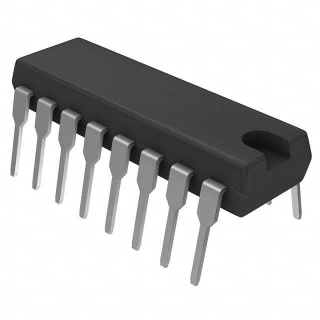
Consulte las especificaciones para obtener detalles del producto.

SN74LS399N
Product Overview
- Category: Integrated Circuit (IC)
- Use: Data Storage and Control
- Characteristics: 8-Bit Latch/Shift Register with 3-State Outputs
- Package: DIP (Dual In-line Package)
- Essence: The SN74LS399N is a versatile IC that combines the functionality of an 8-bit latch and a shift register, with the added feature of 3-state outputs.
- Packaging/Quantity: Available in tubes or reels, with varying quantities depending on the supplier.
Specifications
- Supply Voltage: 4.75V to 5.25V
- Operating Temperature Range: -40°C to +85°C
- Input Voltage High: 2V (min), 0.8V (max)
- Input Voltage Low: 0.8V (min), 0.4V (max)
- Output Voltage High: 2.7V (min), 2.4V (max)
- Output Voltage Low: 0.5V (max)
Detailed Pin Configuration
The SN74LS399N has a total of 20 pins, which are divided into various functional groups:
- GND: Ground pin
- Q0-Q7: Outputs for the 8-bit latch/shift register
- SER: Serial data input
- S0-S3: Shift control inputs
- OE: Output enable input
- MR: Master reset input
- QA-QH: 3-state output buffers
Functional Features
- Combination of Latch and Shift Register: The SN74LS399N can function as an 8-bit latch or a shift register, providing flexibility in data storage and control applications.
- 3-State Outputs: The 3-state outputs allow multiple devices to share a common bus without interfering with each other, enhancing system efficiency.
- Master Reset: The master reset input (MR) allows for the simultaneous clearing of all registers, ensuring a controlled start-up state.
- Shift Control Inputs: The shift control inputs (S0-S3) enable various modes of operation, such as parallel loading, serial shifting, and cascading multiple devices.
Advantages and Disadvantages
Advantages: - Versatility: Combines latch and shift register functionality in a single IC. - 3-State Outputs: Facilitates bus sharing and improves system efficiency. - Easy Integration: Compatible with other TTL logic families, making it easy to incorporate into existing designs.
Disadvantages: - Limited Output Current: The SN74LS399N has a relatively low output current capability, which may restrict its use in certain high-current applications. - Power Consumption: Compared to more modern ICs, the SN74LS399N may consume more power due to its older technology.
Working Principles
The SN74LS399N operates based on the principles of digital logic. It consists of flip-flops that can store data and shift it through the register. The shift control inputs determine the mode of operation, allowing data to be loaded in parallel or shifted serially. The 3-state outputs enable the device to drive external circuitry without causing conflicts on shared buses.
Detailed Application Field Plans
The SN74LS399N finds applications in various fields, including:
- Data Storage Systems: Used in memory units and data registers for temporary storage and retrieval of information.
- Serial-to-Parallel Conversion: Converts serial data streams into parallel formats, enabling efficient processing by other components.
- Bus Sharing: Facilitates communication between multiple devices connected to a common bus, such as in microcontrollers and computer systems.
- Shift Register Applications: Used in applications requiring sequential data shifting, such as LED displays, counters, and frequency dividers.
Detailed and Complete Alternative Models
- SN74LS595: 8-bit shift register with output latches and 3-state outputs.
- CD4094: 8-bit serial-in, parallel-out shift register with 3-state outputs.
- 74HC595: 8-bit shift register with output latches and 3-state outputs, compatible with CMOS logic families.
These alternative models offer similar functionality to the SN74LS399N and can be used as replacements in various applications.
Word count: 511 words
Enumere 10 preguntas y respuestas comunes relacionadas con la aplicación de SN74LS399N en soluciones técnicas
Sure! Here are 10 common questions and answers related to the application of SN74LS399N:
Q: What is SN74LS399N? A: SN74LS399N is a 4-bit universal shift register with parallel inputs and outputs, commonly used in digital logic circuits.
Q: What is the maximum clock frequency for SN74LS399N? A: The maximum clock frequency for SN74LS399N is typically around 25 MHz.
Q: How many data inputs does SN74LS399N have? A: SN74LS399N has four data inputs (D0, D1, D2, and D3) which can be used to load data into the shift register.
Q: Can SN74LS399N be used as a bidirectional shift register? A: Yes, SN74LS399N can be used as a bidirectional shift register by using the appropriate control signals.
Q: What is the purpose of the clear input (CLR) in SN74LS399N? A: The clear input (CLR) is used to reset the shift register to its initial state, clearing all the stored data.
Q: How many output pins does SN74LS399N have? A: SN74LS399N has four output pins (Q0, Q1, Q2, and Q3) which provide the shifted data.
Q: Can SN74LS399N be cascaded to create larger shift registers? A: Yes, multiple SN74LS399N chips can be cascaded together to create larger shift registers with more bits.
Q: What is the power supply voltage range for SN74LS399N? A: The power supply voltage range for SN74LS399N is typically between 4.75V and 5.25V.
Q: What is the maximum output current for SN74LS399N? A: The maximum output current for SN74LS399N is typically around 8 mA.
Q: Can SN74LS399N be used in both synchronous and asynchronous applications? A: Yes, SN74LS399N can be used in both synchronous and asynchronous applications, depending on the control signals used.
Please note that these answers are general and may vary based on specific datasheet specifications or application requirements.

