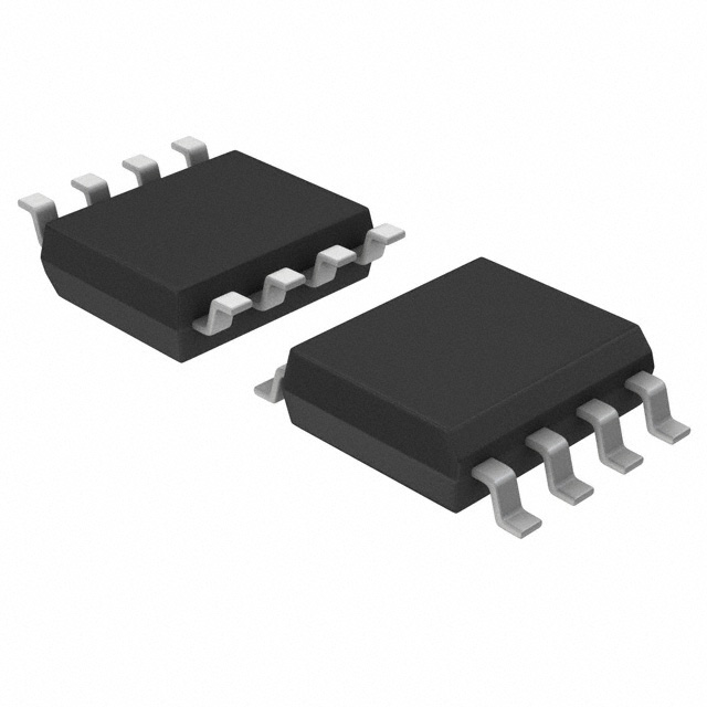
Consulte las especificaciones para obtener detalles del producto.

TL5001AQDR
Product Overview
- Category: Integrated Circuit (IC)
- Use: Voltage Mode PWM Controller
- Characteristics: High-performance, adjustable frequency, and duty cycle control
- Package: SOIC-16
- Essence: Regulates the output voltage of power supplies
- Packaging/Quantity: Tape and Reel, 2500 units per reel
Specifications
- Input Voltage Range: 7V to 40V
- Output Voltage Range: 2.5V to 36V
- Operating Temperature Range: -40°C to +85°C
- Switching Frequency Range: 100Hz to 500kHz
- Maximum Duty Cycle: 100%
- Quiescent Current: 8mA
Detailed Pin Configuration
The TL5001AQDR has a total of 16 pins. The pin configuration is as follows:
- COMP: Compensation pin for feedback loop
- CS: Current sense input pin
- RT/CT: Timing resistor/capacitor connection pin
- GND: Ground reference pin
- VREF: Reference voltage output pin
- VCC: Positive supply voltage input pin
- OSC: Oscillator timing capacitor connection pin
- SYNC: Synchronization input pin
- SS/TR: Soft-start/Shutdown control pin
- OUT: Output pin
- FB: Feedback input pin
- NC: No Connection
- NC: No Connection
- NC: No Connection
- NC: No Connection
- NC: No Connection
Functional Features
- Adjustable frequency and duty cycle control
- Voltage mode control with pulse-width modulation (PWM)
- Overvoltage protection
- Undervoltage lockout
- Soft-start capability
- Error amplifier with high gain
Advantages and Disadvantages
Advantages
- Wide input voltage range allows for versatile applications
- High-performance regulation of output voltage
- Adjustable frequency and duty cycle provide flexibility in power supply design
- Overvoltage protection ensures the safety of connected devices
- Soft-start capability reduces inrush current during startup
Disadvantages
- Requires external components for proper operation
- Limited maximum duty cycle may restrict certain applications
- Not suitable for high-power applications due to its package size
Working Principles
The TL5001AQDR is a voltage mode PWM controller that regulates the output voltage of power supplies. It operates by comparing the feedback voltage from the output with a reference voltage. The error amplifier amplifies the difference between these voltages, which is then used to control the duty cycle of the PWM signal. By adjusting the duty cycle, the TL5001AQDR maintains a stable output voltage.
Detailed Application Field Plans
The TL5001AQDR is commonly used in various applications, including:
- Switching Power Supplies: Provides efficient voltage regulation in power supply units for electronic devices.
- Battery Chargers: Controls the charging process and ensures proper voltage levels for different battery types.
- LED Lighting: Enables dimming and brightness control in LED lighting systems.
- Motor Control: Regulates the speed and direction of motors in industrial and automotive applications.
- Audio Amplifiers: Maintains a stable power supply for audio amplification circuits.
Detailed and Complete Alternative Models
- TL494: Similar voltage mode PWM controller with adjustable frequency and duty cycle control.
- UC3843: Integrated circuit for controlling switch-mode power supplies with adjustable frequency and duty cycle.
- SG3525: PWM controller IC with adjustable frequency and duty cycle for power supply applications.
- LT1241: High-performance PWM controller with adjustable frequency and duty cycle for power electronics.
- MC34063A: Step-up, step-down, and inverting switching regulator controller with adjustable frequency and duty cycle.
These alternative models offer similar functionality and can be used as substitutes for the TL5001AQDR in various applications.
Word count: 464 words
Enumere 10 preguntas y respuestas comunes relacionadas con la aplicación de TL5001AQDR en soluciones técnicas
Sure! Here are 10 common questions and answers related to the application of TL5001AQDR in technical solutions:
Q1: What is TL5001AQDR? A1: TL5001AQDR is a voltage mode PWM controller IC commonly used in power supply applications.
Q2: What is the operating voltage range of TL5001AQDR? A2: The operating voltage range of TL5001AQDR is typically between 7V and 40V.
Q3: What is the maximum output current that TL5001AQDR can handle? A3: TL5001AQDR itself does not have a specific maximum output current rating. It depends on the external components used in the circuit.
Q4: Can TL5001AQDR be used for both step-up and step-down converter designs? A4: Yes, TL5001AQDR can be used for both step-up (boost) and step-down (buck) converter designs.
Q5: What is the frequency range of the PWM signal generated by TL5001AQDR? A5: The frequency range of the PWM signal generated by TL5001AQDR is typically between 100Hz and 500kHz.
Q6: How can I adjust the output voltage using TL5001AQDR? A6: The output voltage can be adjusted by changing the feedback resistors connected to the FB pin of TL5001AQDR.
Q7: Does TL5001AQDR have built-in protection features? A7: Yes, TL5001AQDR has built-in protection features such as overvoltage protection (OVP), undervoltage lockout (UVLO), and thermal shutdown.
Q8: Can TL5001AQDR operate in a synchronized mode? A8: Yes, TL5001AQDR can operate in a synchronized mode by connecting an external oscillator to the SYNC pin.
Q9: What is the maximum duty cycle that TL5001AQDR can achieve? A9: The maximum duty cycle that TL5001AQDR can achieve is typically around 90%.
Q10: Can TL5001AQDR be used in battery charging applications? A10: Yes, TL5001AQDR can be used in battery charging applications by implementing appropriate control and protection circuitry.
Please note that these answers are general and may vary depending on specific application requirements.

