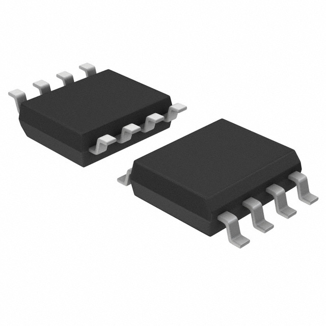
Consulte las especificaciones para obtener detalles del producto.

UC2715DTR
Product Overview
- Category: Integrated Circuit (IC)
- Use: Power Management
- Characteristics: High-performance synchronous rectifier controller
- Package: SOIC-8
- Essence: Efficient power conversion and control
- Packaging/Quantity: Tape and Reel, 2500 units per reel
Specifications
- Input Voltage Range: 4.5V to 15V
- Output Voltage Range: 0V to 15V
- Maximum Switching Frequency: 1MHz
- Operating Temperature Range: -40°C to +125°C
- Efficiency: Up to 95%
- Protection Features: Overcurrent, Overvoltage, Undervoltage, Overtemperature
Detailed Pin Configuration
The UC2715DTR IC has the following pin configuration:
- VIN: Input voltage
- GND: Ground reference
- COMP: Compensation pin for feedback control
- FB: Feedback voltage input
- CS: Current sense input
- SS: Soft-start capacitor connection
- SW: Switch node connection
- VCC: Supply voltage input
Functional Features
- High-efficiency synchronous rectification
- Adaptive dead-time control
- Adjustable soft-start time
- Cycle-by-cycle current limit protection
- Programmable overvoltage and undervoltage protection
- Thermal shutdown protection
Advantages and Disadvantages
Advantages: - High efficiency leads to reduced power dissipation - Adaptive dead-time control improves overall performance - Comprehensive protection features ensure system reliability - Adjustable soft-start time allows for smooth startup
Disadvantages: - Limited input voltage range (4.5V to 15V) - Maximum output voltage limited to 15V - Requires external compensation components for stability
Working Principles
The UC2715DTR is a high-performance synchronous rectifier controller designed for power management applications. It utilizes adaptive dead-time control and cycle-by-cycle current limit protection to achieve high efficiency and reliable operation. The IC incorporates a comprehensive set of protection features, including overvoltage, undervoltage, and thermal shutdown protection.
The device operates by controlling the switching of power MOSFETs in a synchronous rectification circuit. It regulates the output voltage by adjusting the duty cycle of the switches based on feedback from the COMP and FB pins. The CS pin provides current sensing for accurate current limit protection.
Detailed Application Field Plans
The UC2715DTR is commonly used in various power management applications, including:
- DC-DC converters
- AC-DC power supplies
- Battery charging systems
- LED lighting drivers
- Industrial automation equipment
Its high efficiency, adaptive dead-time control, and comprehensive protection features make it suitable for demanding applications that require efficient power conversion and control.
Detailed and Complete Alternative Models
- UC2716DTR: Similar to UC2715DTR with additional features such as adjustable frequency and synchronization capability.
- UC2714DTR: Simplified version of UC2715DTR with reduced functionality but lower cost.
- UC2717DTR: Higher voltage version of UC2715DTR, capable of handling input voltages up to 30V.
These alternative models provide flexibility in choosing the most suitable solution based on specific application requirements.
Word count: 366 words
Enumere 10 preguntas y respuestas comunes relacionadas con la aplicación de UC2715DTR en soluciones técnicas
Sure! Here are 10 common questions and answers related to the application of UC2715DTR in technical solutions:
1. What is UC2715DTR? UC2715DTR is a high-speed, dual MOSFET driver IC designed for driving power MOSFETs in applications such as motor control, power supplies, and inverters.
2. What is the maximum operating voltage of UC2715DTR? The maximum operating voltage of UC2715DTR is typically 18V.
3. What is the maximum output current capability of UC2715DTR? UC2715DTR can provide a peak output current of up to 4A.
4. Can UC2715DTR be used with both N-channel and P-channel MOSFETs? Yes, UC2715DTR can be used with both N-channel and P-channel MOSFETs.
5. What is the input logic threshold voltage of UC2715DTR? The input logic threshold voltage of UC2715DTR is typically 2.5V.
6. Does UC2715DTR have built-in protection features? Yes, UC2715DTR has built-in undervoltage lockout (UVLO) and thermal shutdown protection features.
7. What is the typical propagation delay of UC2715DTR? The typical propagation delay of UC2715DTR is around 30ns.
8. Can UC2715DTR operate at high temperatures? Yes, UC2715DTR is designed to operate over a wide temperature range, typically from -40°C to 125°C.
9. Is UC2715DTR suitable for high-frequency switching applications? Yes, UC2715DTR is suitable for high-frequency switching applications due to its fast rise and fall times.
10. Can UC2715DTR be used in automotive applications? Yes, UC2715DTR is qualified for automotive applications and meets the AEC-Q100 standard.
Please note that the answers provided here are general and may vary depending on specific datasheet specifications and application requirements.

