

Consulte las especificaciones para obtener detalles del producto.
TC74ACT138P(F)
Product Overview
- Category: Integrated Circuit (IC)
- Use: Decoder/Demultiplexer
- Characteristics: High-speed, low-power, 3-to-8 line decoder/demultiplexer
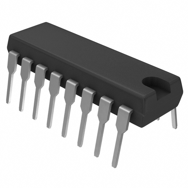
- Package: DIP (Dual In-line Package) or SOP (Small Outline Package)
- Essence: Decodes a three-bit binary input to one of eight outputs
- Packaging/Quantity: Available in tubes or reels, quantity varies based on supplier
Specifications
- Supply Voltage: 2.0V to 6.0V
- Input Voltage: 0V to VCC
- Output Voltage: 0V to VCC
- Operating Temperature Range: -40°C to +85°C
- Propagation Delay Time: 5ns (typical)
- Output Current: ±24mA
- Power Dissipation: 500mW (max)
Detailed Pin Configuration
The TC74ACT138P(F) has a total of 16 pins, which are assigned as follows:
- GND (Ground)
- A0 (Address Input Bit 0)
- A1 (Address Input Bit 1)
- A2 (Address Input Bit 2)
- /G1 (Enable Input 1)
- /G2A (Enable Input 2A)
- /G2B (Enable Input 2B)
- Y0 (Output 0)
- Y1 (Output 1)
- Y2 (Output 2)
- Y3 (Output 3)
- Y4 (Output 4)
- Y5 (Output 5)
- Y6 (Output 6)
- Y7 (Output 7)
- VCC (Positive Power Supply)
Functional Features
- High-speed operation allows for quick decoding of input signals
- Low-power consumption makes it suitable for battery-powered devices
- 3-to-8 line decoding capability provides flexibility in addressing multiple outputs
- Enable inputs (/G1, /G2A, /G2B) allow for selective activation of outputs
- Outputs (Y0-Y7) can drive standard TTL or CMOS logic levels
Advantages and Disadvantages
Advantages: - High-speed operation enables efficient signal decoding - Low-power consumption extends battery life in portable devices - Flexible addressing options with 3-to-8 line decoding - Compatibility with TTL and CMOS logic levels
Disadvantages: - Limited to 3-bit binary input, restricting the number of possible combinations - May require additional components for complex decoding applications
Working Principles
The TC74ACT138P(F) is a decoder/demultiplexer IC that converts a three-bit binary input into one of eight possible outputs. The input address bits (A0, A1, A2) determine which output line (Y0-Y7) is activated. The enable inputs (/G1, /G2A, /G2B) control the overall operation of the IC.
When the enable inputs are active (low), the selected output line corresponding to the input address is enabled and driven to a low logic level. All other output lines remain high. When the enable inputs are inactive (high), all output lines are disabled and remain at a high logic level.
Detailed Application Field Plans
The TC74ACT138P(F) can be used in various applications, including:
- Address decoding in microcontrollers and microprocessors
- Memory selection in RAM and ROM systems
- Data routing in multiplexing applications
- Signal demultiplexing in communication systems
- Control signal generation in digital circuits
Detailed and Complete Alternative Models
Some alternative models to the TC74ACT138P(F) include:
- 74HC138: Similar functionality, but operates at a lower voltage range (2V to 6V)
- CD74AC138: Higher-speed version with a propagation delay of 3ns
- SN74LS138: Compatible with TTL logic levels, suitable for mixed-logic systems
These alternative models offer similar decoding capabilities and can be used as substitutes based on specific requirements.
Word count: 511 words
Enumere 10 preguntas y respuestas comunes relacionadas con la aplicación de TC74ACT138P(F) en soluciones técnicas
Sure! Here are 10 common questions and answers related to the application of TC74ACT138P(F) in technical solutions:
Q: What is TC74ACT138P(F)? A: TC74ACT138P(F) is a 3-to-8 line decoder/demultiplexer integrated circuit (IC) that can be used in various digital logic applications.
Q: What is the purpose of TC74ACT138P(F)? A: The purpose of TC74ACT138P(F) is to decode binary information from three input lines into eight output lines, making it useful for addressing multiple devices or selecting one of eight outputs.
Q: How does TC74ACT138P(F) work? A: TC74ACT138P(F) works by using its three input lines (A0, A1, and A2) to select one of the eight output lines (Y0-Y7) based on the binary code applied to the inputs.
Q: What is the voltage range supported by TC74ACT138P(F)? A: TC74ACT138P(F) supports a voltage range of 2.0V to 5.5V, making it compatible with a wide range of digital systems.
Q: Can TC74ACT138P(F) be used in both TTL and CMOS logic systems? A: Yes, TC74ACT138P(F) is designed to be compatible with both TTL and CMOS logic systems, allowing for versatile integration into different types of circuits.
Q: What is the maximum output current of TC74ACT138P(F)? A: The maximum output current of TC74ACT138P(F) is typically 24mA, which allows it to drive standard logic levels.
Q: Can TC74ACT138P(F) be cascaded to increase the number of output lines? A: Yes, TC74ACT138P(F) can be cascaded with other decoders to increase the number of output lines and address more devices.
Q: Does TC74ACT138P(F) have any built-in protection features? A: Yes, TC74ACT138P(F) has built-in diode clamps on its inputs to protect against static discharge and voltage spikes.
Q: What is the operating temperature range of TC74ACT138P(F)? A: The operating temperature range of TC74ACT138P(F) is typically -40°C to 85°C, allowing it to function in a wide range of environments.
Q: Are there any application notes or reference designs available for TC74ACT138P(F)? A: Yes, the manufacturer of TC74ACT138P(F) provides application notes and reference designs that can help users understand and implement the IC in their technical solutions.
Please note that these answers are general and may vary depending on the specific datasheet and manufacturer's documentation for TC74ACT138P(F).