

Consulte las especificaciones para obtener detalles del producto.
IRF540
Product Overview
Category
The IRF540 belongs to the category of power MOSFETs (Metal-Oxide-Semiconductor Field-Effect Transistors).
Use
It is commonly used as a switching device in electronic circuits, particularly in power supply and motor control applications.
Characteristics
- High voltage capability
- Low on-resistance
- Fast switching speed
- High input impedance
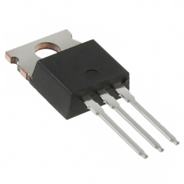
Package
The IRF540 is typically available in a TO-220 package, which allows for easy mounting on heat sinks.
Essence
The essence of the IRF540 lies in its ability to efficiently control high-power loads in various electronic systems.
Packaging/Quantity
It is usually packaged in reels or tubes, with quantities varying based on manufacturer specifications.
Specifications
- Drain-Source Voltage (VDS): 100V
- Continuous Drain Current (ID): 33A
- On-Resistance (RDS(on)): 0.077Ω
- Power Dissipation (PD): 150W
- Gate-Source Voltage (VGS): ±20V
- Operating Temperature Range: -55°C to 175°C
Detailed Pin Configuration
The IRF540 has three pins: 1. Gate (G): Input terminal for controlling the flow of current between the drain and source. 2. Drain (D): Output terminal through which the current flows out of the MOSFET. 3. Source (S): Terminal through which the current enters the MOSFET.
Functional Features
- High input impedance allows for easy interfacing with control circuits.
- Fast switching speed enables efficient control of power flow.
- Low on-resistance minimizes power loss and heat generation.
Advantages and Disadvantages
Advantages
- High voltage capability makes it suitable for high-power applications.
- Low on-resistance results in minimal power dissipation.
- Fast switching speed enhances overall system efficiency.
Disadvantages
- Susceptible to damage from static electricity if mishandled.
- Requires careful consideration of gate drive circuitry for optimal performance.
Working Principles
The IRF540 operates based on the principle of field-effect modulation, where the flow of current between the drain and source is controlled by the voltage applied to the gate terminal.
Detailed Application Field Plans
The IRF540 finds extensive use in the following applications: - Switching power supplies - Motor control circuits - Audio amplifiers - LED lighting systems - DC-DC converters
Detailed and Complete Alternative Models
Some alternative models to the IRF540 include: - IRF640: Higher voltage rating - IRF530: Lower voltage rating - IRF4905: Complementary P-channel MOSFET
In conclusion, the IRF540 is a versatile power MOSFET with a wide range of applications, offering high voltage capability, low on-resistance, and fast switching speed. Its robust characteristics make it an essential component in various electronic systems, especially those requiring efficient power control and management.
[Word Count: 426]
Enumere 10 preguntas y respuestas comunes relacionadas con la aplicación de IRF540 en soluciones técnicas
What is the IRF540 transistor used for?
- The IRF540 is a power MOSFET transistor commonly used in electronic circuits to switch high-power loads such as motors, solenoids, and lamps.
What are the key specifications of the IRF540 transistor?
- The IRF540 has a maximum drain-source voltage (Vds) of 100V, continuous drain current (Id) of 33A, and low on-resistance (Rds(on)).
How do I connect the IRF540 in a circuit?
- The IRF540 is typically connected in a circuit using a gate driver to control the voltage applied to its gate terminal, and with appropriate protection diodes to prevent voltage spikes.
Can the IRF540 be used for PWM (Pulse Width Modulation) applications?
- Yes, the IRF540 is suitable for PWM applications due to its fast switching characteristics and low Rds(on), making it efficient for controlling high-power loads with variable duty cycles.
What are the common applications of the IRF540 in technical solutions?
- The IRF540 is commonly used in motor control, power supply circuits, DC-DC converters, and automotive applications.
How do I calculate the power dissipation in an IRF540 circuit?
- The power dissipation in the IRF540 can be calculated using the formula P = I^2 * Rds(on), where I is the drain current and Rds(on) is the on-resistance of the transistor.
What are the typical thermal considerations for the IRF540?
- Proper heat sinking and thermal management are important for the IRF540 to ensure that it operates within its specified temperature limits, especially in high-power applications.
Are there any common failure modes associated with the IRF540?
- Common failure modes include overvoltage or overcurrent conditions leading to thermal runaway, as well as potential damage from voltage spikes if not properly protected.
Can the IRF540 be used in parallel to increase current handling capability?
- Yes, multiple IRF540 transistors can be connected in parallel to share the load current and increase the overall current handling capability of the circuit.
What are some best practices for driving the IRF540 in a circuit?
- It's important to use proper gate drive circuitry, including appropriate gate resistors and decoupling capacitors, to ensure reliable and stable operation of the IRF540 in a circuit.